
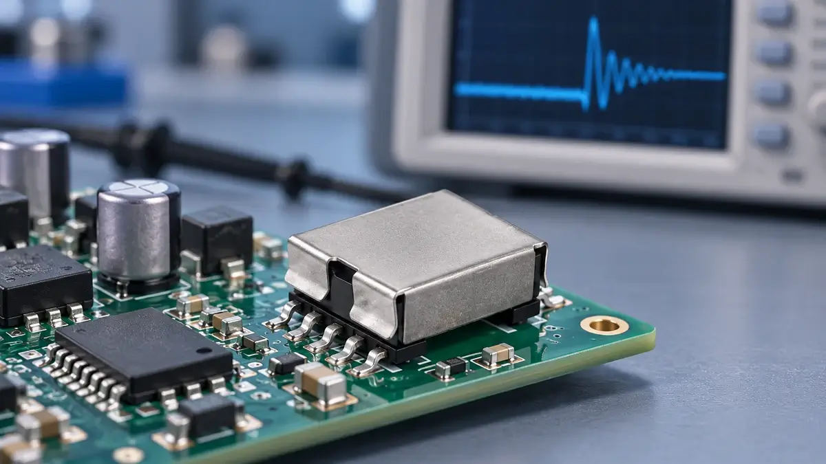
When shortlisting a compact EFD flyback transformer, the catalog turns ratio is a starting point, not a guarantee of auxiliary-rail voltage at every load. The regulated output can look normal while a lightly loaded controller-bias winding runs high. That does not automatically mean the transformer has the wrong turns: leakage inductance and parasitic capacitance may ring after switch turn-off, allowing the auxiliary rectifier to charge its reservoir capacitor toward a transient peak.
This guide uses LPEMA's compact EP/EFD product selection as its practical context. It separates peak charging from controller light-load behavior and measurement artifacts, then shows what to specify before requesting a sample. It does not assume a fault, power rating, or insulation performance for any particular part.
Start with an LPEMA EFD flyback transformer shortlist
The LPEMA EFD product table lists EFD15 and EFD20 flyback candidates with input, output, turns-ratio, and primary-inductance fields. Several EFD15 rows show a three-part ratio, useful for identifying a candidate with a bias winding. That table does not specify auxiliary voltage across every line and load condition, nor does it establish the behavior of a tested unit.
Filter first for the input range, regulated output, power class, footprint, and height of the actual supply. Then confirm whether the bias winding powers the controller VCC and request the winding drawing, polarity, pin map, and test conditions. A catalog ratio is not a substitute for a light-load cross-regulation test; no catalog part is being claimed to exhibit the fault discussed here.
What makes a flyback auxiliary winding voltage rise at light load?
The ideal turns ratio predicts winding voltage during energy transfer, but the rectified capacitor may capture a higher transient peak. Power Integrations' multiple-output flyback guide describes how interwinding leakage and parasitic capacitance produce ringing; with little auxiliary load, the rectifier can charge the capacitor above the nominal value. The contrast is especially useful to test when the main output is heavily loaded while the auxiliary rail is light.
TI's multi-output flyback article identifies leakage inductance as a major cause of poor cross-regulation and discusses winding placement and coupling. These are design levers, not a diagnosis for a particular transformer without waveforms and load data.
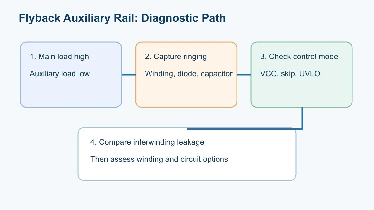
A four-step diagnostic sequence
1. Sweep the main and auxiliary loads independently
At fixed input, record main-full/aux-light, main-light/aux-full, and intermediate combinations. If auxiliary DC voltage rises with main load and falls with added auxiliary load, investigate cross-regulation and peak charging first. Testing only both outputs at rated load can miss the condition.
2. Compare winding waveform with rectified DC voltage
Observe the auxiliary winding, diode, and storage capacitor using an appropriate isolated probe and short return connection. Separate the turn-off spike, damped ringing, diode conduction interval, and capacitor voltage. A long probe ground lead can create apparent ringing, so record the measurement setup.
3. Check controller light-load and supply thresholds
Burst mode, pulse skipping, startup, and undervoltage thresholds change auxiliary charging and discharge. If controller VCC repeatedly rises and falls, check controller state and its VCC network. Changing turns before identifying the mode can create low-line startup failure.
4. Measure coupling under defined port conditions
Record primary-to-main, primary-to-auxiliary, and main-to-auxiliary equivalent leakage under specified shorting and test-frequency conditions. One unspecified total leakage number cannot explain the difference between the regulated and auxiliary outputs.
Transformer and circuit options
| Option | Potential benefit | Recheck before release |
|---|---|---|
| Reposition auxiliary winding | Change coupling to regulated output | Isolation, winding process, leakage, capacitance |
| Add minimum auxiliary load | Reduce light-load peak charging | Standby loss and heating |
| Post-regulate auxiliary rail | Hold controller or bias voltage | Loss, headroom, component rating |
| Adjust rectifier or damping | Limit transient capture | Startup, loss, full-load behavior |
Power Integrations' bias-winding troubleshooting note discusses a series resistor and winding-order changes when a leakage spike degrades load regulation. Values and topology must follow the controller and prototype tests.
On small EP/EFD bobbins, window area, insulation, and pins are limited. Better coupling may increase winding work, change capacitive coupling, or compromise spacing. The related EFD17 pin-mapping article lists the polarity, pin, and drawing checks needed when winding order changes. Different core sizes or catalog entries are not interchangeable on name alone.
What to send LPEMA before requesting an EP/EFD sample
After selecting a mechanical and electrical shortlist from the EFD product table, specify a load matrix for every output at minimum, nominal, and maximum input. State steady-state voltage limits, startup peak, allowed duration, controller, light-load mode, schematic, winding table, polarity dots, auxiliary winding position, leakage test connections, and test frequency. Prototype acceptance should include turns ratio, primary inductance, interwinding leakage, DCR, temperature rise, and project-specific insulation requirements; these cannot be inferred from the cover illustration or package appearance.
If the auxiliary winding powers the controller, verify absolute maximum VCC, UVLO, and startup behavior in that controller's datasheet. A transformer that starts in one setup is not yet validated across the application envelope. The LPEMA custom transformer specification guide helps organize controlled winding and test revisions.
FAQ
Should I reduce auxiliary turns when the rail is too high?
Not before separating the turns-ratio voltage from ringing and light-load peak charging. Fewer turns can cause insufficient VCC at low line or normal load.
Will a preload resistor fix it?
It may lower the rail but adds standby loss and may hide coupling or controller behavior. Verify all line, load, and temperature cases.
Is the EP or EFD core family the cause?
The core family alone cannot establish the cause. Winding order, insulation, rectifier behavior, PCB layout, and control mode determine the result.
Conclusion
For an LPEMA EP/EFD flyback transformer project, use the product table to shortlist candidates, then map load combinations and capture winding and DC-rail waveforms before changing magnetics. Send LPEMA candidate part numbers, controller details, waveforms, load matrix, winding drawing, and mechanical limits so the sample and acceptance conditions can be evaluated for the actual application.

