
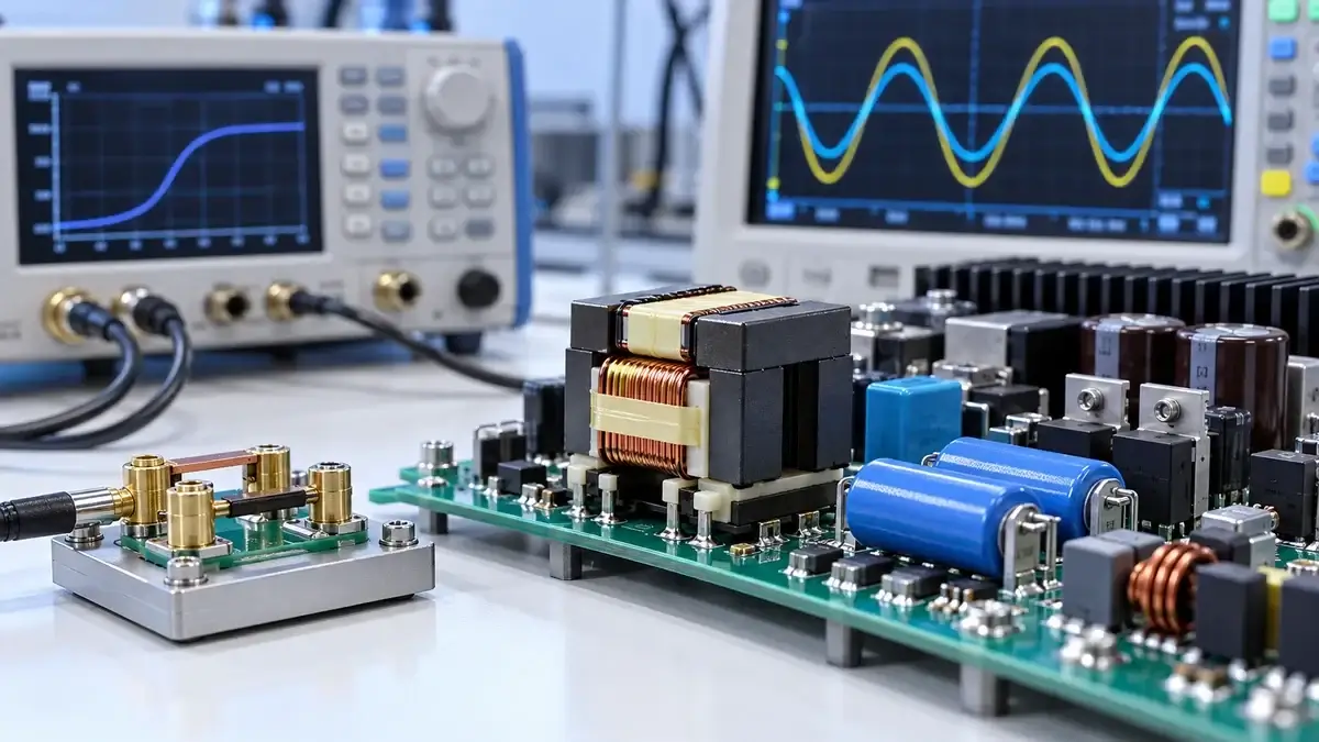
In an LLC resonant converter, magnetizing inductance Lm and resonant inductance Lr may both be implemented in one high-frequency transformer, but they do different jobs. Treating open-circuit primary inductance, short-circuit leakage inductance, and the model parameters Lm and Lr as interchangeable is a common reason calculated gain and resonant frequency miss the hardware result.
This guide connects the LLC equivalent circuit to discrete and integrated magnetics, measurement connections, tolerance, and prototype waveforms.
What Lm and Lr do in the LLC tank
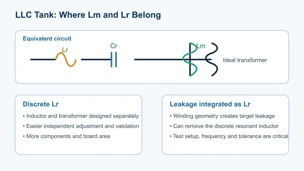
The familiar LLC tank contains series resonant inductance Lr, resonant capacitance Cr, and transformer magnetizing inductance Lm. Lr and Cr set the main resonance, approximately `fr = 1 / (2π√(LrCr))`. Lm forms a parallel branch that shapes below-resonance gain, magnetizing circulating current, and the current available to commutate MOSFET output capacitance during dead time.
TI's LLC efficiency material identifies Lr, Lm, and Cr as the resonant network and shows that integrated magnetics can implement leakage-based Lr and Lm on one core. Infineon's 3.3-kW LLC design guide derives transformer and tank parameters from gain, load, and frequency requirements.
Magnetizing inductance is not simply “higher is better”
Lower Lm produces more magnetizing current. That can widen ZVS margin, but it raises RMS circulating current, copper loss, and conduction loss. Higher Lm reduces circulation but can weaken light-load or low-line ZVS margin and change the achievable gain range.
TI's 90-W LLC reference design explains how energy in Lm maintains current during dead time and helps commutate the MOSFET nodes before turn-on. This cannot be judged from an inductance number alone; input voltage, frequency, dead time, MOSFET Coss, and load range all matter.
Designers often use `Ln = Lm/Lr`. A lower ratio tends to give a steeper gain characteristic and higher magnetizing circulation. A higher ratio reduces circulation but may narrow regulation or ZVS margin in some operating regions. The converter design should set this ratio; the transformer supplier should not choose it in isolation.
When leakage inductance becomes the resonant inductor
Leakage is normally treated as a transformer parasitic. In an LLC converter it can intentionally implement some or all of Lr. Integration removes a discrete inductor and can reduce PCB area and interconnect loss, but it makes the tank sensitive to winding placement, assembly, and production spread.
TI's article on LLC frequency error shows why an ideal-transformer model becomes inaccurate when transformer leakage implements Lr. A model including coupling and primary/secondary leakage is needed. A datasheet “leakage inductance” value cannot be dropped into the model without confirming measurement side and referral convention.
Discrete Lr versus integrated leakage
| Implementation | Advantages | Main risks |
|---|---|---|
| Separate resonant inductor plus tightly coupled transformer | Lr and Lm are easier to design, measure, and trim independently | More parts, volume, loss, and cost |
| Transformer leakage used as Lr | Compact; removes a magnetic component and connections | Higher sensitivity to leakage tolerance and winding consistency |
| Integrated magnetic paths with adjustable Lr/Lm | Can combine density with parameter control | More complex magnetic design, gaps, simulation, and manufacturing |
Power Integrations' HiperLCS-2 design guide describes a chambered transformer construction that intentionally creates leakage for the LLC tank and explains why winding placement matters. Compare efficiency, density, EMI, manufacturability, parameter tolerance, and tuning effort—not component count alone.
How to measure Lm and leakage inductance
Every report should state test terminals, unused-winding condition, frequency, AC level, equivalent model, and temperature.
Open-circuit measurement
Measuring from the selected primary with all other windings open gives the input inductance seen at that port. It is often close to the primary magnetizing-related design value, but the real model still contains leakage, loss, and capacitance. The open-circuit result is not universally identical to a pure Lm element.
Short-circuit measurement
Short the specified secondary with very low impedance and measure the residual inductance from the primary. The shorting fixture, center-tap connection, unused secondaries, and frequency all affect the result. Confirm whether the converter model uses primary leakage, total referred leakage, or the sum of a discrete inductor and transformer leakage.
The open/short and fixture-compensation principles in the LPEMA transformer LCR measurement guide are also useful here even though the transformer application is different.
Why measured resonant frequency misses the calculation
Common causes include:
- actual Lr includes primary and referred secondary leakage, a discrete inductor, and PCB parasitics;
- Lm, Lr, and Cr tolerance and temperature shift the tank;
- coupling makes the simple ideal-transformer model inaccurate;
- MOSFET Coss, rectifier capacitance, and winding capacitance enter the real network;
- small-signal LCR conditions differ from operating frequency, waveform, and current;
- center-tapped halves have unequal leakage and create half-cycle asymmetry.
During debugging, capture switching frequency, half-bridge node, resonant current, primary voltage, output voltage, and temperature rise together. Changing Cr until one operating point matches can hide a magnetics or modeling error.
What an LLC transformer specification should contain
Define input/output range, rated power, half- or full-bridge drive, nominal and min/max frequency, ratio, target Lm, target equivalent Lr, any external inductor, measurement connections and frequency, tolerances and temperature range, Cr and tolerance, core/gap constraints, winding construction, DCR, insulation, and temperature-rise limits.
If leakage implements Lr, add allowable production distribution and center-tap half matching. The LPEMA custom transformer RFQ guide can help organize drawings, test conditions, and sample acceptance criteria.
FAQ
Is short-circuit inductance automatically the LLC Lr?
It is the equivalent leakage seen from a specified port with a specified short and test frequency. Whether it equals model Lr depends on referral, external inductance, center-tap construction, and the chosen equivalent circuit.
Does lower Lm always improve ZVS?
Lower Lm increases magnetizing current and may widen ZVS margin, but it also increases RMS circulation, copper loss, and conduction loss. Validate the complete line, load, and temperature range.
Is an integrated Lr always more efficient than a discrete resonant inductor?
No. Integration removes a component and connections, but uncontrolled leakage spread, fringing field, AC winding loss, or thermal concentration can reduce efficiency and repeatability.
Conclusion
Lm and Lr are not interchangeable inductance readings. Lm shapes gain, circulating current, and ZVS; Lr combines with Cr to set the main resonance and may come from a discrete inductor, transformer leakage, or an integrated magnetic path.
For an LLC transformer review, submit the topology, controller, input/output range, power, frequency, Lm/Lr/Cr definitions, measurement conditions, and mechanical constraints through the LPEMA contact page. LPEMA can evaluate a compact high-frequency or custom magnetic path; final values must be verified in the actual tank and thermal environment.

