
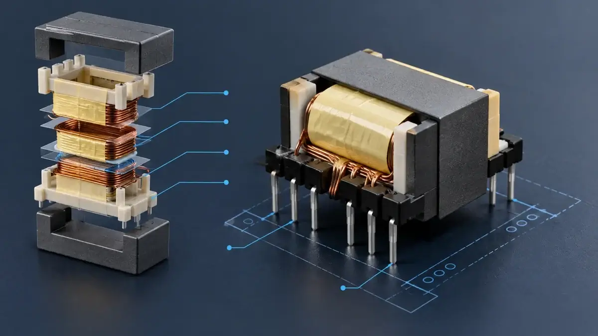
An EFD17-class transformer can fit a height-constrained auxiliary power board, but matching the core family does not make two parts interchangeable. In a multi-output flyback transformer, pin mapping also controls winding segregation, creepage paths, rectifier-loop length, polarity, and PCB routability.
This guide explains how to define winding-to-pin relationships, mechanical drawings, and prototype acceptance criteria before sourcing a custom EFD17 multi-output transformer. It does not assign an unsupported power or insulation rating; capability depends on frequency, material, gap, winding construction, temperature rise, and end-equipment requirements.
Why EFD17 is used on low-profile control boards
The EFD family uses a flattened center-leg geometry and matching bobbin to provide winding area within a lower profile. Exact effective area, window, dimensions, and tolerances must come from the selected core and bobbin drawings. TDK's EFD core information and Ferroxcube material data help establish core-family and material context, but they do not replace finished-transformer validation.
Compared with an EP construction, EFD is commonly considered when component height and a two-row terminal layout are priorities. EP constructions are often considered where compact shielding and small volume matter. The choice should follow PCB height, board area, winding count, and isolation partitioning—not the core name alone.
Map windings before assigning pin numbers
A multi-output flyback may contain a primary, bias winding, and several isolated outputs. Before writing Pin 1 or Pin 2, define:
- each winding function, ratio, and reference ground;
- which outputs are isolated and which share a return;
- polarity dots and rectifier direction;
- winding proximity and segregation requirements;
- the feedback or bias winding used for regulation;
- reserved pins, barriers, or creepage paths.
The TI UCC28740 datasheet shows the typical relationship among primary, auxiliary, and rectified secondary windings in a flyback supply. A real multi-output design must also account for cross-regulation, leakage spikes, rectifier drops, and load combinations.
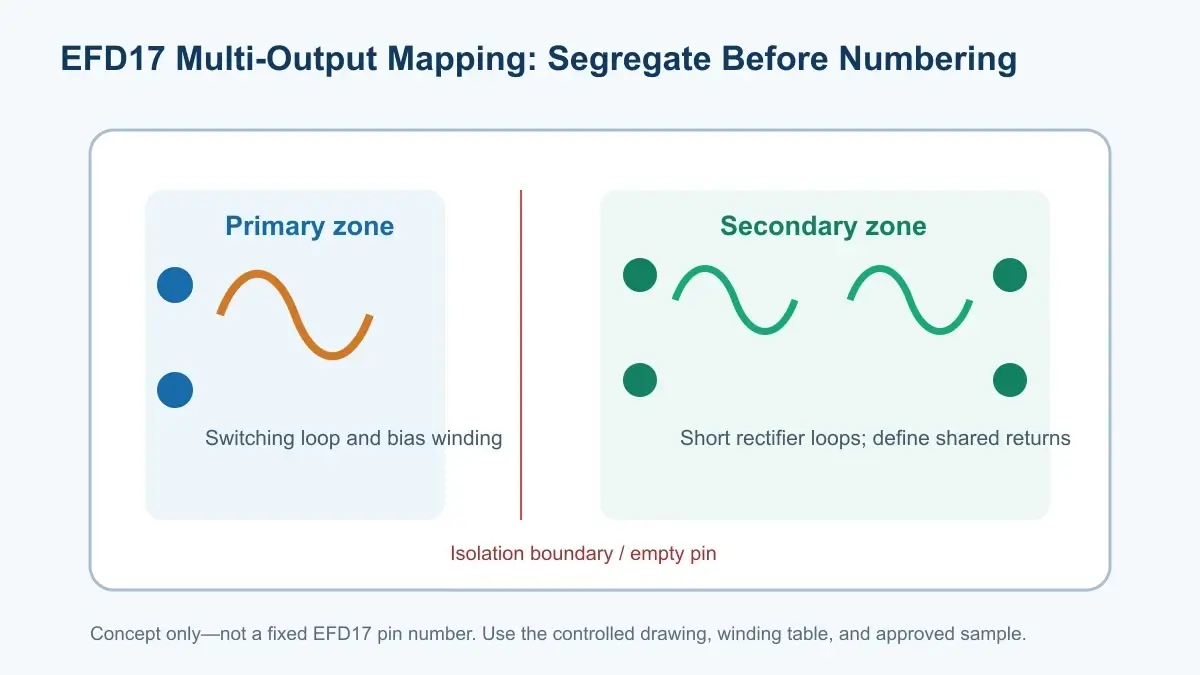
Five constraints that shape an EFD17 pin map
1. Physically separate primary and secondary terminals
Place primary terminals on one side and isolated secondaries on the other whenever the bobbin permits. If routing or pin count forces a crossover, define sleeving, flying leads, barriers, and spacing in controlled drawings. Never infer an insulation rating from the name EFD17.
2. Keep high-frequency current loops short and paired
Long leads in primary switching and secondary rectifier loops add parasitic inductance. Place winding start and finish pins near the associated power devices. Pin order must be developed with the PCB layout, not decided by the transformer supplier in isolation.
3. Make polarity traceable
Wrong winding polarity can reverse bias power or rectifier operation. Schematics, winding tables, and mechanical drawings should use the same dot convention, and prototype reports should confirm polarity electrically.
4. Account for shared returns and cross-regulation
Common-ground outputs may share a return pin, but combined current can add terminal and copper-drop error. Fully isolated outputs require more pins and spacing. Test light- and heavy-load combinations, not only the all-outputs-rated condition.
5. Treat unused pins as design resources
An empty pin position can increase primary-secondary separation, provide a path for an insulated lead, or reduce coupling from a high-dv/dt node. Filling every position can work against isolation and layout goals.
What belongs on an EFD17 supplier drawing
| Drawing field | Definition required |
|---|---|
| Top and bottom views | Pin 1 mark, numbering direction, assembly orientation |
| PCB footprint | Hole diameter, pitch, keep-out, and tolerance |
| Winding table | Start, finish, polarity dot, ratio, and conductor |
| Electrical limits | Lp, leakage, DCR, ratio, and test conditions |
| Insulation boundary | Working voltage, hipot, creepage, clearance, system standard |
| Thermal boundary | Ambient, cooling, rise limit, measurement location |
| Prototype gate | Polarity, pins, waveform, temperature, abnormal modes |
Use the LPEMA custom transformer specification guide to submit the circuit, PCB height, operating range, outputs, and load combinations. For EP5, EP6, EP7, or EFD17 constructions, the supplier should evaluate the complete requirement rather than quote from the package name alone.
PCB placement and incoming inspection
Place switching and rectifier loops close to their corresponding pins, and avoid routing high-dv/dt copper under the isolation region. If an electrostatic shield is required, specify its connection and prevent a closed shorted turn. Test every important output-load combination during prototype validation.
Incoming inspection should cover height, pitch, pin diameter and straightness, Pin 1, polarity, ratio, primary inductance, leakage, and DCR. After approval, tie the mechanical drawing, winding revision, and test method to the same part-number revision.
FAQ
Does EFD17 imply a fixed power rating?
No. Power capability depends on topology, frequency, material, gap, temperature rise, winding loss, and cooling.
Can an existing EFD17 PCB footprint be reused?
Do not assume so. Babbins can differ in pitch, pin diameter, pin count, and Pin 1 orientation. Verify a controlled drawing and physical sample.
Are more secondary outputs always better?
No. Every winding consumes window, terminals, and isolation space while increasing cross-regulation and test complexity. Include only outputs the system actually needs.
Conclusion
EFD17 offers a useful low-profile form, but successful customization depends on designing winding relationships, pin mapping, isolation partitioning, and PCB current loops together. A core-family name is not a complete specification, and a functional prototype is not automatically production-qualified.
For an EFD17 or compact EP-series transformer review, submit topology, frequency, input/output range, winding count, height limit, pin drawing, and insulation requirements through the LPEMA contact page.

