
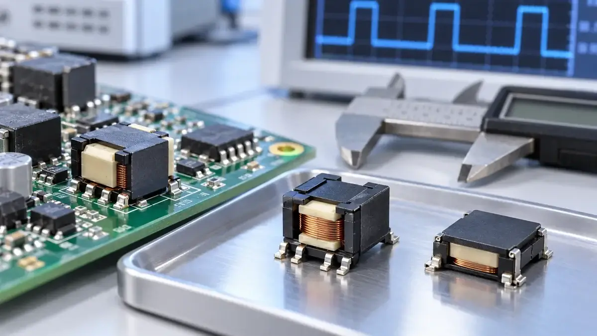
Package size and a 1:1 ratio are only screening filters when selecting an SMD gate drive transformer supplier. Reliable MOSFET, IGBT, or SiC gate drive depends on volt-second capability, magnetizing inductance, leakage inductance, interwinding capacitance, insulation construction, and production consistency.
This supplier-qualification guide covers surface-mount pulse GDTs that transfer gate commands directly. It does not treat the transformer inside an isolated gate-driver bias DC/DC supply as the same component.
1. Confirm the transformer function
A pulse GDT drives the gate network and must transfer turn-on and turn-off pulses while resetting its core. An auxiliary gate-driver transformer feeds a rectified, often regulated isolated bias supply. Both may use compact EP or ER SMT packages, but their specifications are different.
Write “pulse gate drive transformer” in the RFQ and include the controller, primary drive stage, power switch, and gate network. If the requirement is an auxiliary-supply transformer, specify the converter topology, input/output rails, and power separately.
2. Qualify the package for automated assembly
An EP5 or ER9.5 label does not replace a controlled mechanical drawing. Compare body dimensions, terminal locations, land pattern, pin numbering, dot orientation, coplanarity, tape orientation, and reel details. A sample that can be hand-soldered is not automatically suitable for pick-and-place and reflow production.
The Würth Elektronik WE-GDT catalog lists EP5, ER9.5, and 1210 SMT constructions and provides drawings, CAD, and EDA files. Documentation completeness is itself a supplier criterion: production sourcing needs revision-controlled data, not only a product photo.
3. Define ratio and polarity from the required gate waveform
Turns ratio describes the ideal voltage relationship. Actual gate amplitude also depends on driver impedance, magnetizing current, winding resistance, leakage inductance, gate charge, and external resistance. Multiple-secondary designs need an unambiguous dot convention and pin definition for every winding.
Require pin-to-pin winding definitions and polarity on the drawing. Validate the primary and the voltage at the power-switch gate under load; an open-circuit secondary measurement does not prove gate performance.
4. Check volt-seconds and core reset
A GDT cannot sustain DC. Long-term imbalance between positive and negative primary volt-seconds shifts core flux; startup, current limit, and fault pulses may be more severe than steady state. TI's GDT design note explains why average transformer voltage should approach zero.
Provide primary voltage, minimum and maximum frequency, maximum continuous pulse width, duty-cycle range, reset method, and startup/fault timing. The supplier should state a volt-second rating or another verifiable boundary instead of only a recommended frequency.
5. Compare magnetizing inductance with test conditions
Magnetizing inductance sets magnetizing current and driver loading. A value is comparable only when frequency, AC level, temperature, equivalent model, and unused-winding condition match.
Require test terminals, open-winding state, frequency, level, model, and tolerance. Incoming inspection should use the same method. The LPEMA GDT LCR measurement guide details repeatable connections.
6. Do not optimize leakage in isolation
Leakage inductance limits edge current and resonates with gate-loop capacitance. Tighter or bifilar coupling may reduce leakage while increasing primary-to-secondary capacitance. TI's discussion of GDT parasitics describes this trade-off.
Before comparing numbers, confirm which secondary was shorted, the shorting fixture, frequency, and fixture compensation. An undocumented “typical leakage” value is not a reliable supplier ranking metric.
7. Treat interwinding capacitance as a high-dv/dt parameter
In SiC and fast MOSFET stages, interwinding capacitance carries displacement current across the isolation barrier, approximately `iCM = Cps × dv/dt`. Lower capacitance can support common-mode and EMI performance, but it trades against leakage, size, insulation spacing, and repeatability.
Request terminal grouping, unused-winding state, frequency, fixture, and shielding. Würth's WE-GDT parametric data includes leakage, interwinding capacitance, and volt-seconds together—an example of why ratio and hipot alone are insufficient.
8. Separate hipot from insulation design
A one-time dielectric test is not continuous working voltage and does not by itself establish basic or reinforced insulation. The equipment designer must define working voltage, transients, pollution degree, altitude, creepage, clearance, and target standards.
Ask the supplier to document wire, bobbin, tape or barrier construction, minimum distances, dielectric test voltage and duration, and whether production testing is 100%. Never transfer a competitor's certification claim to a custom construction.
9. Validate temperature, DCR, and solder reliability together
Smaller packages reduce copper and heat-dissipation area. Primary and secondary DCR, magnetizing current, and gate load all contribute loss. Test temperature rise at maximum ambient, pulse width, and continuous frequency while documenting PCB copper and airflow.
For SMT production, obtain the recommended reflow profile, solder-heat limit, terminal finish, and storage conditions. Inspect post-reflow coplanarity, opens, terminal movement, appearance, and electrical drift.
10. Use process evidence to judge production capability
Ask how turns, winding order, tension, insulation layers, core gap, adhesive, and polarity are controlled. Confirm control plans, first-article approval, lot traceability, and change notification for custom parts. If a quality-system qualification is required, request current evidence covering the actual manufacturing site and scope—do not assume it.
Supplier comparison matrix
| Area | Required before quotation | Prototype verification |
|---|---|---|
| Application | Switch part, gate network, primary waveform | Gate amplitude, edge, ringing, false turn-on |
| Magnetics | Ratio, Lm, volt-seconds, reset | Primary current, pulse droop, temperature |
| Parasitics | Leakage/capacitance and methods | Switch-node common-mode and EMI trend |
| Insulation | Working voltage, construction, spacing | Dielectric, creepage/clearance, system review |
| Mechanical | Drawing, land pattern, coplanarity, reel | Placement, reflow, AOI, solder joints |
| Production | Tolerances, controls, traceability, changes | Multi-sample distribution and lot consistency |
FAQ
Is the same SMD package enough for a drop-in replacement?
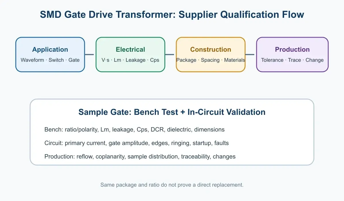
No. Polarity, volt-seconds, Lm, leakage, capacitance, DCR, and insulation can differ even when outline and ratio match. Complete item-by-item and dynamic validation first.
What should be measured on initial samples?
At minimum, record ratio and polarity, Lm, leakage, interwinding capacitance, DCR, dielectric test, and critical dimensions. Then test steady-state, startup, and fault waveforms on the real board, preserving all test conditions.
Is an LPEMA part a direct cross for a competitor number?
That claim cannot be made without complete specifications and system validation. A competitor drawing, actual waveforms, and system requirements can start a candidate review; only testing can establish suitability.
Conclusion
Choosing an SMD gate drive transformer supplier is not a search for a visually similar 1:1 component. It is a check that the supplier can convert waveform, volt-second, parasitic, insulation, and SMT manufacturing requirements into a controlled production specification.
To evaluate a compact EP, ER, or other SMT GDT construction, send the switch part number, schematic, primary and gate waveforms, insulation boundary, mechanical limits, and annual volume through the LPEMA contact page. LPEMA can screen a standard construction or custom-sample path; final suitability remains subject to validation in the customer's circuit.

