
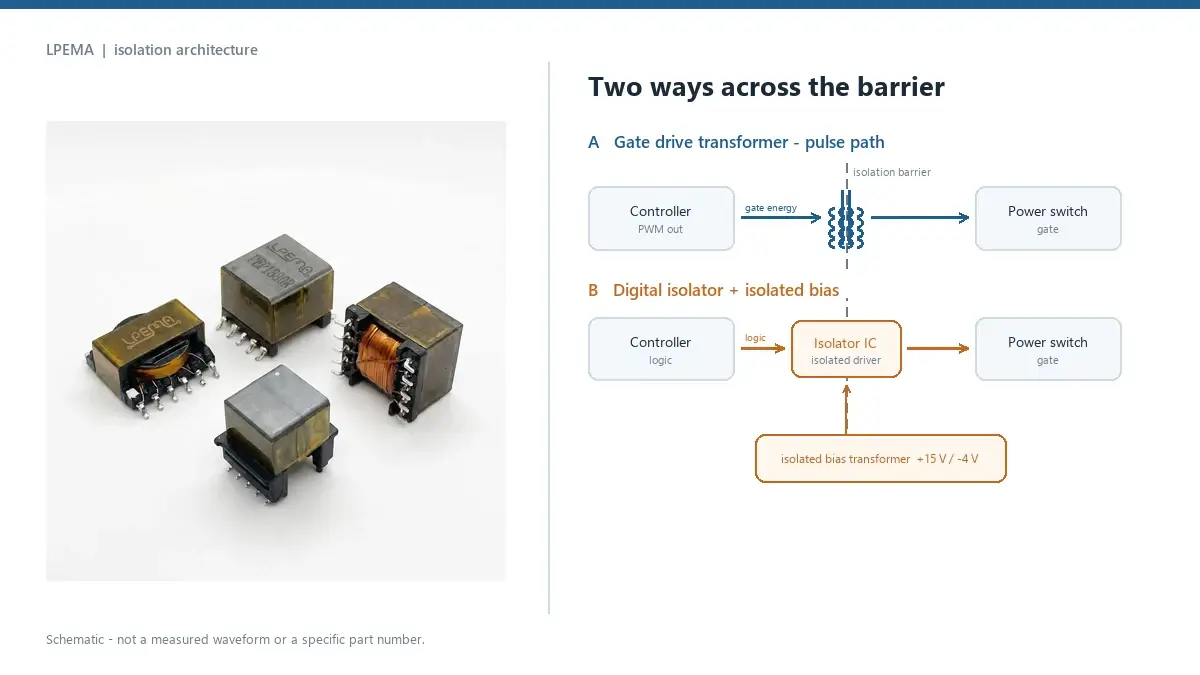
A gate drive transformer and a digital isolator are often drawn in the same place on a block diagram, between the controller and the power switch, and that is where the confusion starts. They do not do the same job. One of them carries gate energy; the other carries information and needs energy from somewhere else, and that single difference runs through every gate drive transformer vs digital isolator comparison you will read.
The gate drive transformer vs digital isolator decision is therefore not a component swap. It is a decision about the isolation architecture of the whole gate driver: where the pulse comes from, where the gate charge comes from, what happens when the controller stops switching, and which standard the barrier has to be qualified against. Get that architecture wrong and the bill of materials can look perfectly reasonable while the first prototype shows a saturated core, a false turn-on, or a gate that stays high in a fault state.
This article lays out the two paths as they actually behave in SiC, IGBT, and MOSFET designs, then gives the test sequence that settles the choice before a layout is frozen.
The question is really two questions
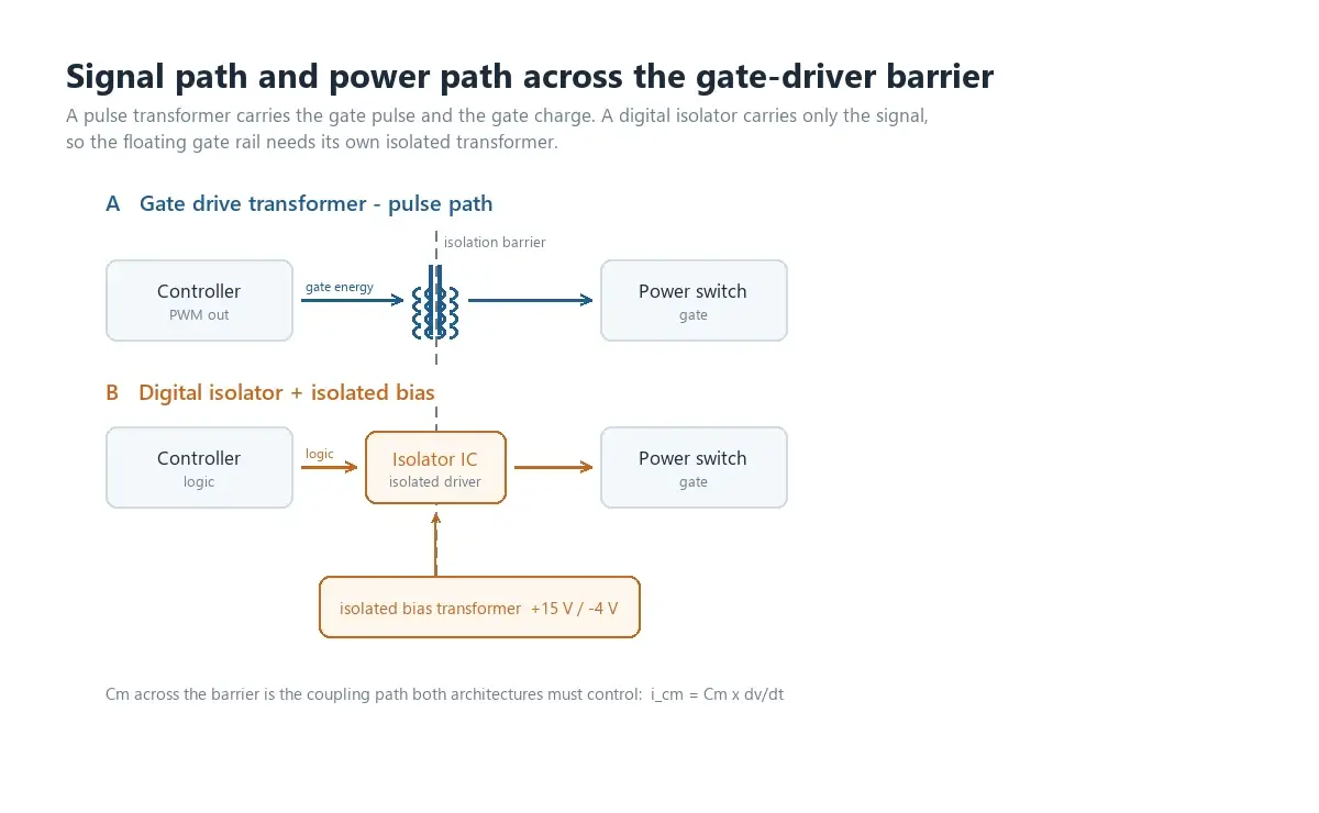
An isolated gate driver needs two things to reach a power switch across an isolation barrier:
- An isolated signal path, which tells the switch when to turn on and off.
- An isolated power path, which delivers the gate charge for every switching event, and the steady bias current of the driver stage.
A gate drive transformer can supply both at once, because the gate pulse itself is the thing being transmitted. A digital isolator supplies only the first. It transmits a logic-level signal, and the gate charge still has to come from a floating supply built on the isolated side, usually a small transformer driven by a push-pull stage or an LLC stage, as in the isolated bias designs built around transformer drivers such as the TI SN6505B or the TI UCC25800-Q1.
Once you separate signal from power, most of the arguments that circulate online resolve into a single table instead of a debate.
What a gate drive transformer does well
A pulse transformer is a passive, wideband element. The pulse applied to the primary appears at the secondary with no sampling, encoding, or modulation step in between, and with essentially no added latency beyond what leakage inductance and the gate loop impose. In high-frequency half-bridge and full-bridge stages that matters.
Practical strengths:
- One primary, several secondaries. A single transformer drives high-side and low-side switches, and the channel-to-channel timing is set by the winding geometry rather than by two separate signal chains with their own propagation delays.
- Gate energy comes through the barrier. No separate floating rail is needed for the pulse path, which removes one converter and its own isolation requirement from the design.
- Negative off-bias is straightforward. With bipolar drive and a defined reset network, the gate can be held below the source or emitter between pulses, which is often what IGBT turn-off wants.
- The part is simple to qualify thermally. There is no local electronics on the isolated side to protect against the switch node's dv/dt.
The cost is magnetic: a transformer cannot hold a DC level. Duty-cycle extremes, burst mode, startup, current-limit and pulse-skipping states all stress the volt-second balance of the core, and a transformer that survives steady-state operation can still walk into saturation during a protection event. That mechanism, and the reset methods that control it, is covered in our note on volt-second balance and core reset.
What a digital isolator does well
A digital isolator transmits a logic state, including a static one. That single property changes which control schemes are practical:
- Any duty cycle, including 0% and 100%. There is no magnetic limit to observe, so the driver can hold a switch on for an arbitrarily long time, or keep it off indefinitely.
- Independent fault handling. Because the signal path is a data channel, status information such as desaturation detection, overcurrent flags, or a soft-turn-off command can travel back across the barrier.
- Clean behaviour at startup and in burst mode. The driver does not depend on a reset network that has to be correct before the first pulse.
The cost sits on the power side. The floating stage needs a real isolated bias supply with its own transformer, rectifier, and regulation, and that supply has to start reliably, hold up during a fault, and stay within its own creepage and clearance budget. Isolated gate driver families from STMicroelectronics and Analog Devices are built around exactly this assumption: the IC isolates the signal, the system still has to provide the isolated rail.
Gate drive transformer vs digital isolator: side by side
| Decision point | Transformer signal path (GDT) | Digital isolator signal path |
|---|---|---|
| Static level / DC gate state | Not possible; flux must be reset | Possible, including 0% and 100% duty |
| Duty-cycle range | Limited by volt-seconds and reset | Not magnetically limited |
| Gate energy source | Same transformer | Separate isolated bias supply required |
| Channel matching in a half bridge | Set by winding construction | Set by IC channel-to-channel skew spec |
| Common-mode path across barrier | Interwinding capacitance | Barrier capacitance inside the package |
| Typical failure mode | Saturation, tilted pulse, failed reset | Output glitch, lost bias rail |
| Component qualification | Insulation system (IEC 61558 family, UL system recognition) | Isolator component standard (IEC 60747-17 / VDE 0884-17, UL 1577) |
| Board space and part count | One magnetic plus passive reset parts | One IC plus a bias supply with its own transformer |
| Best fit | Fast, high-current, symmetric drive | Wide duty-cycle range, fault telemetry, precise DC behaviour |
Nothing in that table says one column is better. It says the two columns suit different control schemes, and that the power column is where the real system cost hides.
Parasitic capacitance and dv/dt: where the transformer pays a price
Both paths have a capacitance across the barrier, and both have to live with the current it injects. The displacement current is simply
i = C × dv/dt
At 100 V/ns, 3 pF produces 0.3 A of common-mode current; at 5 pF the same edge produces 0.5 A. That current returns somewhere. If it returns through the controller's ground reference or through the gate loop instead of through a controlled path, the result is a disturbed PWM comparator, a spurious edge, or a gate that rings through the threshold.
For a transformer, the capacitance is set by winding construction and the physical gap between primary and secondary: closer coupling lowers leakage inductance and raises capacitance, so the two cannot be optimised independently. Screens, split bobbins, and winding order move the number, and any figure quoted in a datasheet is only meaningful together with the test setup that produced it.
For a digital isolator the same physics applies, but the number lives inside the package and appears in the datasheet as barrier capacitance alongside common-mode transient immunity (CMTI). That makes the comparison easier to specify and harder to change: you can improve a transformer's barrier behaviour by re-winding it, while an isolator's barrier is fixed by the part you selected.
Either way, the honest test is the same: measure the common-mode current in the actual layout with the actual switch, at the actual dv/dt, rather than comparing headline numbers from two different test conditions.
Two standards, two different tests
The insulation question is where datasheet comparisons fail most often, because the two device types are qualified in different ways.
A digital isolator is a component with a defined barrier. Its safety parameters usually come from IEC 60747-17 (published in Germany as VDE 0884-17), which defines repetitive peak, working, transient and surge isolation voltages, partial-discharge limits, and the insulation lifetime basis. A datasheet for a part such as the TI ISO6760 lists these parameters as a group; they are not interchangeable with a dielectric withstand test result.
A discrete transformer is qualified as part of an insulation system. What matters is the wire insulation, the tape and margin construction, the bobbin material, the potting or varnish, the temperature class, and the creepage and clearance actually achieved on the finished part. Those come from the IEC 61558 family, from UL system recognition of the insulation used, and ultimately from the creepage and clearance that the equipment standard requires for the working voltage, pollution degree, and material group of the end product.
The practical consequence: a transformer's hipot voltage and an isolator's working isolation voltage are not the same kind of number, and comparing them directly is meaningless. If you need to know whether a part is acceptable, you need the equipment standard first, then the barrier data that matches it.
The combined architecture most high-power designs converge on
On SiC and high-current IGBT stages, the architecture that keeps winning is a split:
- a digital isolator, or an isolated gate driver IC with the isolator built in, carries the signal and the fault telemetry;
- a small isolated bias transformer, driven by a push-pull or LLC transformer driver, generates the floating rails, typically a positive on-voltage plus a smaller negative off-voltage;
- the gate loop itself is short, local, and designed for the switch's own requirements.
This split removes the transformer from the signal path, so duty-cycle limits disappear, and it shrinks the magnetic to a few watts of bias power. It also moves the transformer's design problem to a place where magnetics manufacturers are strongest: turns ratio, coupling, interwinding capacitance, insulation system, and repeatable production.
If your design stays with a transformer in the signal path, the same engineering discipline applies, and the selection order in our gate drive transformer selection guide is the place to start: waveform and volt-seconds first, parasitics second, insulation last.
Verification before you freeze the architecture
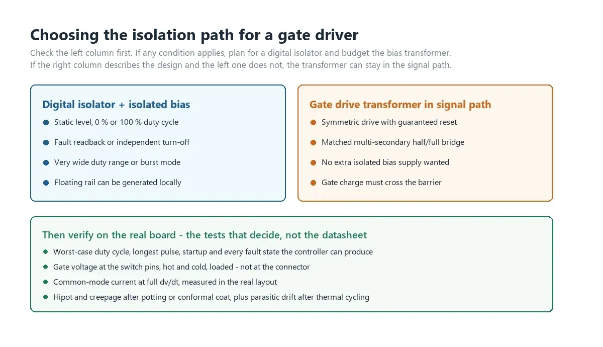
Whichever path you choose, run these checks on the real board before the layout is committed:
- Worst-case switching state. Maximum duty, minimum duty, longest uninterrupted on-time, and any state where the controller stops switching.
- Startup and protection events. Current limit, desaturation trip, soft start, and pulse skipping. A transformer path is at its most vulnerable here.
- Gate voltage under load, hot and cold. Turns ratio and driver supply are only a starting point; measure at the switch pins, not at the connector.
- Common-mode current. Probe the return path or use a current transformer around the gate loop while the switch node moves at full dv/dt.
- Isolation test in the finished assembly. Hipot and partial discharge where applicable, plus the creepage and clearance actually achieved after potting and conformal coat.
- Parasitic drift after environmental stress. Re-measure magnetizing inductance, leakage inductance, and interwinding capacitance after thermal cycling. The LCR measurement method we use in production applies equally here.
If any of those checks changes the answer, the architecture decision was premature. That is normal; the point is to find out before tooling, not after.
What to send when the isolation decision needs a transformer
Whether the transformer ends up in the signal path or in the bias supply, the RFQ has to describe the circuit, not just a footprint. Useful inputs are:
- topology and switching frequency range;
- switch part number and the gate voltage targets, including off-bias;
- the primary waveform: amplitude, duty-cycle range, maximum pulse width;
- isolation requirement: working voltage, test voltage and duration, insulation class, creepage and clearance;
- size limits, mounting, and pinout;
- any reference part, together with the electrical conditions it has to meet.
A dimensional cross-reference is not an electrical equivalence. LPEMA's drive transformer range covers EP5, EP6, EP7, EFD17, SMD CASE, and ER constructions with single and multiple secondaries, so the fastest path is usually to send the circuit conditions and let the construction be chosen from the requirement rather than from a photo. The product pages under industrial control drive transformers list the available families.
FAQ
Is a gate drive transformer the same as a digital isolator?
No. A gate drive transformer transfers the gate pulse itself through magnetic coupling. A digital isolator transfers a logic signal and requires a separate isolated bias supply to actually drive the gate.
Can a gate drive transformer pass a 100% duty cycle?
No. A transformer cannot hold a DC flux level indefinitely. Long on-times, startup states, and pulse skipping all require a defined reset mechanism and enough volt-second margin for the worst-case event, not just steady state.
Why do isolated gate drivers need a separate bias supply?
Because the isolator only carries information. The gate charge for each switching event has to be delivered by a floating supply on the isolated side, which is why isolated driver ICs are almost always paired with a small bias transformer and its driver.
Which has better common-mode transient immunity, a transformer or an isolator?
It depends on the capacitance across the barrier, the layout, and the dv/dt, not on the device category. Measure the common-mode current in the real board and compare it with the immunity level the driver stage actually needs at your switching speed.
Are the isolation ratings of the two device types comparable?
Only in the sense that both describe a barrier. A digital isolator is qualified to a component standard such as IEC 60747-17, while a transformer is qualified as an insulation system together with the creepage and clearance your equipment standard requires. The numbers are not interchangeable.
Can one transformer drive both switches of a half bridge?
Yes, with two correctly phased secondary windings and a reset scheme that holds under the worst-case duty error. Polarity, dead time, and gate voltage must be verified on the actual stage, not only on paper.
When should the design switch to the combined approach?
Whenever the control scheme needs static levels, a very wide duty-cycle range, fault readback, or independent turn-off. At that point the isolator carries the signal and the transformer moves to the bias supply, where its size and cost drop sharply.
Bottom line
The gate drive transformer vs digital isolator question is settled by the control scheme, not by a preference for magnetics or silicon. Decide where the gate energy comes from, list the operating states the driver must survive, check the isolation barrier against the standard your product is actually certified to, and then measure the common-mode current and the gate waveform on the first prototype.
If the answer is a transformer, in the signal path or in the bias supply, send LPEMA the topology, the switch part number, the drive waveform, and the isolation requirement. We will come back with a construction that fits the circuit, or tell you which condition is missing before a sample can be built. Contact LPEMA to start that review.

