
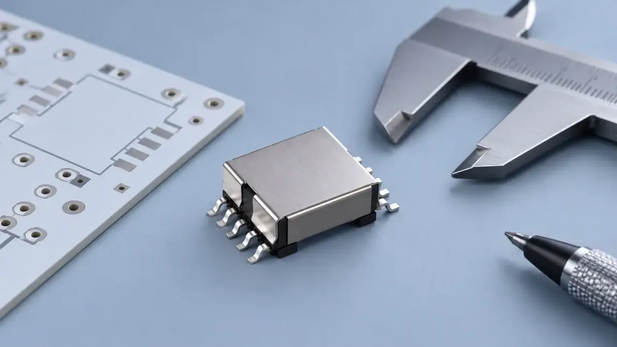
Choosing an EFD15 PoE flyback transformer supplier is not simply a matter of matching a core size or a nominal output voltage. A useful RFQ must let an engineer verify the electrical design, mechanical fit and test method before a purchasing team compares samples. This guide shows what to send LPEMA when evaluating a compact EFD15-class PoE flyback transformer, and what not to infer from a catalog row.
Start with the LPEMA EFD15 PoE flyback transformer range
The LPEMA EFD product table lists EFD15 PoE flyback candidates with fields for input range, output, turns ratio and primary inductance. Use those published entries to shortlist a possible electrical starting point. Do not treat a similar-looking package or a three-part turns ratio as confirmation of pin compatibility, insulation construction, controller compatibility or drop-in replacement status. Ask for the current controlled drawing and datasheet for the exact candidate.
For a new design, first identify the PoE interface, the actual voltage presented to the converter over operating conditions, regulated rail requirements and any auxiliary or bias rail. The transformer is only one part of the isolated converter: controller operating mode, rectifier, clamps, PCB layout and thermal environment all affect the final result.
What should an EFD15 flyback transformer RFQ contain?
| RFQ field | Minimum information to supply | Why the supplier needs it |
|---|---|---|
| Electrical input | Minimum, nominal and maximum converter input; startup and surge conditions | Sets worst-case operating points and insulation review |
| Outputs | Voltage, continuous and peak current, tolerance, load combinations | Defines energy demand and cross-regulation checks |
| Control design | Controller part number, switching-frequency range, DCM/CCM or other operating mode | Determines inductance, peak-current and timing constraints |
| Magnetics | Proposed turns ratio, primary inductance, permitted leakage and DCR test conditions | Prevents comparisons between incompatible measurements |
| Mechanics | PCB land pattern, maximum height, pin map, polarity and drawing revision | Avoids a sample that fits electrically but cannot be assembled |
| Compliance | End-equipment insulation requirement and applicable standard specified by the buyer | Allows a construction review without assuming a catalog claim covers the system |
| Validation | Test fixture, line/load matrix, temperature limits and acceptance criteria | Makes prototype results reproducible |
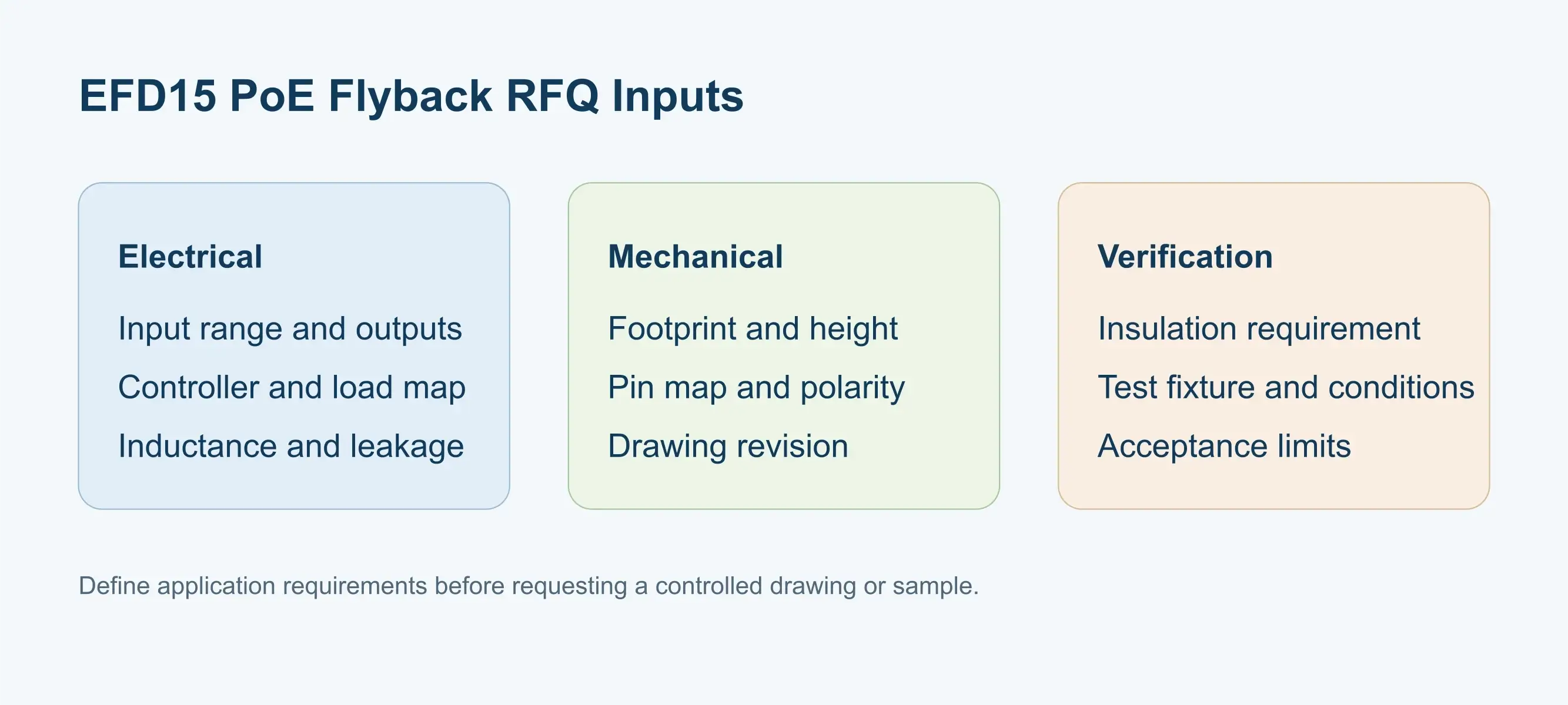
The Coilcraft flyback selection guide emphasizes input range, outputs and primary peak current when choosing a flyback transformer. Its custom transformer worksheet is another example of how buyers can organize design inputs. These are general engineering references, not specifications for LPEMA parts.
How to compare a catalog candidate with a custom sample
Ask the supplier to identify the exact catalog part or proposed custom drawing revision. Compare winding-to-pin mapping and dot polarity before turns ratio. Specify whether primary inductance is measured at a stated frequency and signal level, how leakage is measured with other windings shorted, and the temperature at which DCR is checked. A single unlabeled inductance number is not an acceptance plan.
Next, test at minimum input and maximum load for current and temperature margin, then at light load and mixed-output conditions for bias-rail behavior. The companion auxiliary-winding light-load troubleshooting article explains why a bias rail may run high even when the nominal turns ratio looks appropriate. Neither article claims that a listed EFD15 part has that fault.
If a buyer requests an equivalent to a competitor part, compare controlled drawings and datasheets item by item: footprint, winding functions, polarity, inductance test method, leakage, DCR, insulation construction and application-specific thermal behavior. Without that review and sample validation, call it a candidate for evaluation, not a direct replacement. Bourns' flyback transformer paper illustrates how core and winding choices depend on the target circuit; its examples are not interchangeable specifications for this PoE design.
Questions to resolve before placing a sample order
Can I choose an EFD15 transformer from output power alone?
No. Check input range, controller mode, primary peak current, inductance, mechanical envelope and thermal conditions together. A catalog power figure does not validate your full application.
Does matching the turns ratio make two transformers interchangeable?
No. Pin assignment, polarity, insulation, leakage, DCR and winding construction can still differ. Verify the exact drawing and prototype behavior.
What should I send LPEMA first?
Send the converter schematic, candidate part number if any, input/output matrix, controller, switching conditions, PCB footprint, height limit, safety requirement and requested test criteria. The LPEMA custom specification guide helps structure that package, and the contact page is the route for a drawing and sample discussion.
The sourcing decision
A good EFD15 PoE flyback transformer RFQ connects a published candidate to a controlled drawing and a reproducible sample test. Use the LPEMA product table for initial filtering, then agree the application-specific electrical, insulation and mechanical requirements before ordering. The cover is an editorial illustration based on an EFD product reference, not a photograph or performance record of a listed part.

