
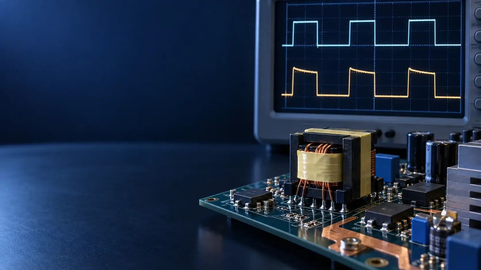
A gate drive transformer can isolate and transfer gate-drive pulses, but it cannot hold a DC high level indefinitely like a digital isolator. The turns ratio is not the limit. The core must receive alternating positive and negative volt-seconds so its flux returns to a repeatable operating region every cycle.
If a forward pulse lasts too long, reset voltage is insufficient, or startup and fault states create asymmetric pulses, flux can walk in one direction. The result may be rising magnetizing current, pulse droop, waveform distortion, and eventually core saturation.
Why a gate drive transformer cannot pass continuous DC
Faraday's law requires changing magnetic flux for transformer action. When voltage is applied to the primary, flux change is related to both voltage and duration. For a rectangular pulse, the engineering quantity is straightforward: volt-seconds = primary voltage × pulse duration.
If the primary remains at one polarity, flux keeps moving in one direction. As the core approaches its usable flux range, magnetizing current can rise rapidly and the secondary waveform no longer reproduces the intended gate pulse.
Texas Instruments' *Why use a Gate Drive Transformer?* explains that the average voltage across a gate drive transformer must be approximately zero. Selection must check worst-case volt-seconds and pulse droop, not merely switching frequency and turns ratio.
Volt-second balance does not always mean exactly 50% duty cycle
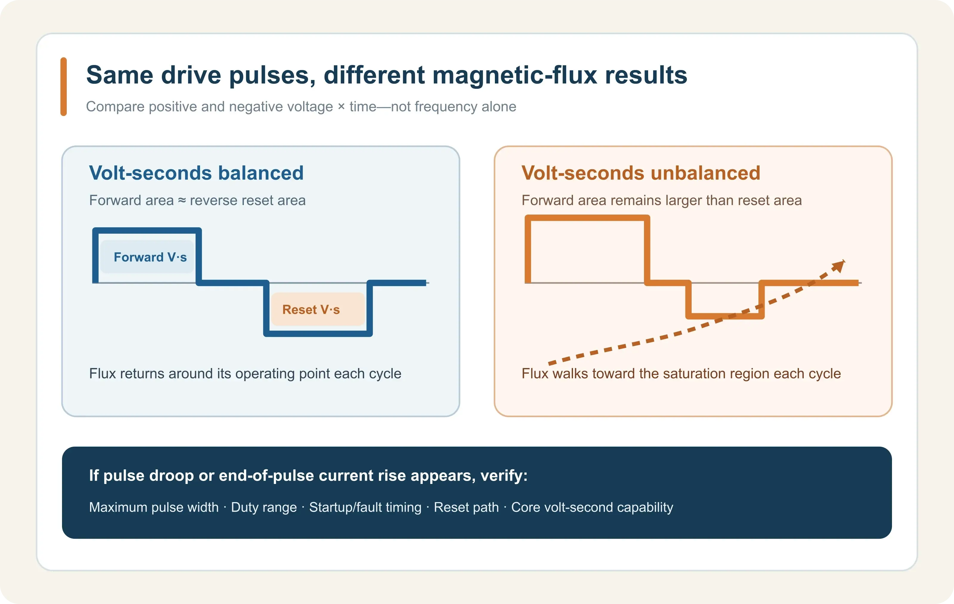
The essential requirement is that positive and negative voltage-time areas cancel over a complete repeating cycle:
| Operating condition | Forward volt-seconds | Reset volt-seconds | Risk |
|---|---|---|---|
| Similar voltage and duration | Approximately equal | Approximately equal | Flux resets each cycle |
| Forward pulse becomes longer | Increases | Unchanged | Flux walks toward one side |
| Reset voltage decreases | Unchanged | Decreases | More reset time is required |
| Same-polarity startup pulses | Accumulates | Insufficient | Worst case occurs before steady state |
Push-pull drives and implementations used with LLC or phase-shifted full-bridge converters often produce alternating excitation naturally. That does not guarantee balance at the transformer terminals. Driver propagation mismatch, dead time, output-stage voltage drop, winding resistance, and startup or protection sequences can all change the actual volt-seconds.
A wide duty-cycle range may require a primary DC-blocking capacitor and a secondary DC-restoration or clamp network. These additions need validation of turn-off voltage, reset current, and transient stress. Adding a capacitor alone does not prove that every abnormal state is safe.
Maximum continuous pulse width matters more than nominal frequency
Switching frequency defines the period but does not define magnetic stress by itself. Two systems can both operate at 100kHz while one has a maximum same-polarity pulse of 2µs and another produces a 7µs pulse during startup or current limiting. Their required volt-second margins are very different.
Determine the actual primary voltage
Use the voltage at the transformer primary terminals, not only the nominal driver supply. Driver high-side and low-side drops, series resistors, and winding DCR change the effective applied voltage.
Find the longest same-polarity interval in every state
Check normal operation, startup, soft start, light-load burst or pulse skipping, current limiting, short-circuit protection, shutdown, and controller reset. The longest pulse may occur during a transition rather than at the nominal operating point.
Verify reset polarity, amplitude, and time
“Low level” does not describe a reset mechanism. Confirm whether the primary receives reverse voltage during the off interval, its amplitude and duration, and whether clamp diodes, the gate network, or secondary loading alter the reset path.
Waveforms that can indicate inadequate reset or flux walk
Primary current bends upward near the end of the pulse
In the linear region, magnetizing current changes with an approximately constant slope. A pronounced increase in slope near the pulse end is one reason to investigate core saturation. Driver current limiting, probe bandwidth, and the measurement loop can produce similar shapes, so one trace alone is not conclusive.
The current baseline drifts over consecutive cycles
A single cycle may appear normal while unequal positive and negative volt-seconds shift the current center over many cycles. Capture a sufficiently long record and observe primary voltage, primary current, and gate voltage together.
Gate-pulse amplitude droops or collapses
Higher magnetizing current increases voltage drop across driver output resistance, series resistance, and winding resistance. Low magnetizing inductance, excessive gate charge, or inadequate driver peak current can create similar symptoms. Use the gate drive transformer waveform-distortion guide to separate these causes.
Laboratory validation must include abnormal states
Capture at least these synchronized waveforms:
- voltage directly across the transformer primary;
- primary current and its baseline over multiple cycles;
- gate-to-source or gate-to-emitter voltage at the power device;
- switch-node voltage to correlate common-mode transients and Miller coupling;
- continuous startup, shutdown, current-limit, and fault-recovery records.
Testing should cover input-voltage limits, temperature boundaries, and the longest pulse sequence allowed by the controller. With multiple secondaries, compare every channel because loading and PCB layout can produce different gate waveforms.
Both TI's *Fundamentals of MOSFET and IGBT Gate Driver Circuits* and Infineon's isolated gate-driving note treat gate drive as a system problem involving driver capability, device input characteristics, parasitics, and PCB current paths.
Information required for transformer selection
“1:1, 100kHz, 15V” is not enough for reliable selection or replacement:
| Required information | Why it matters |
|---|---|
| Primary voltage and drive method | Determines actual volt-seconds and driver stress |
| Maximum positive and negative pulse duration | Defines flux swing and reset margin |
| Duty range, dead time, and startup sequence | Reveals asymmetry and transient states |
| Reset, DC-blocking, and clamp circuit | Shows how flux returns to its starting point |
| Complete power-device part number | Provides gate charge and gate-voltage limits |
| Number of secondaries and turns ratio | Defines architecture and load distribution |
| Isolation, creepage, and dimensional limits | Establishes construction and safety boundaries |
| Measured primary and gate waveforms | Separates transformer and external-circuit issues |
Use the LPEMA gate drive transformer selection guide to organize requirements, then review the New Energy, PV & Energy Storage magnetics page for application categories. Series and package names are only an initial filter; final suitability depends on the real waveform and insulation constraints.
Conclusion
A gate drive transformer cannot hold a high output indefinitely because its core needs adequate reverse volt-seconds to reset every cycle. The important variables are actual primary voltage, maximum continuous pulse width, positive and negative volt-seconds, reset path, and startup and fault timing—not switching frequency alone.
When pulse droop, rising end-of-pulse current, or multi-cycle baseline drift appears, evaluate core reset together with magnetizing inductance, driver capability, and the external gate loop. For design or replacement review, submit the power-device part number, waveforms, timing, isolation requirements, and mechanical limits through the LPEMA contact page.

