
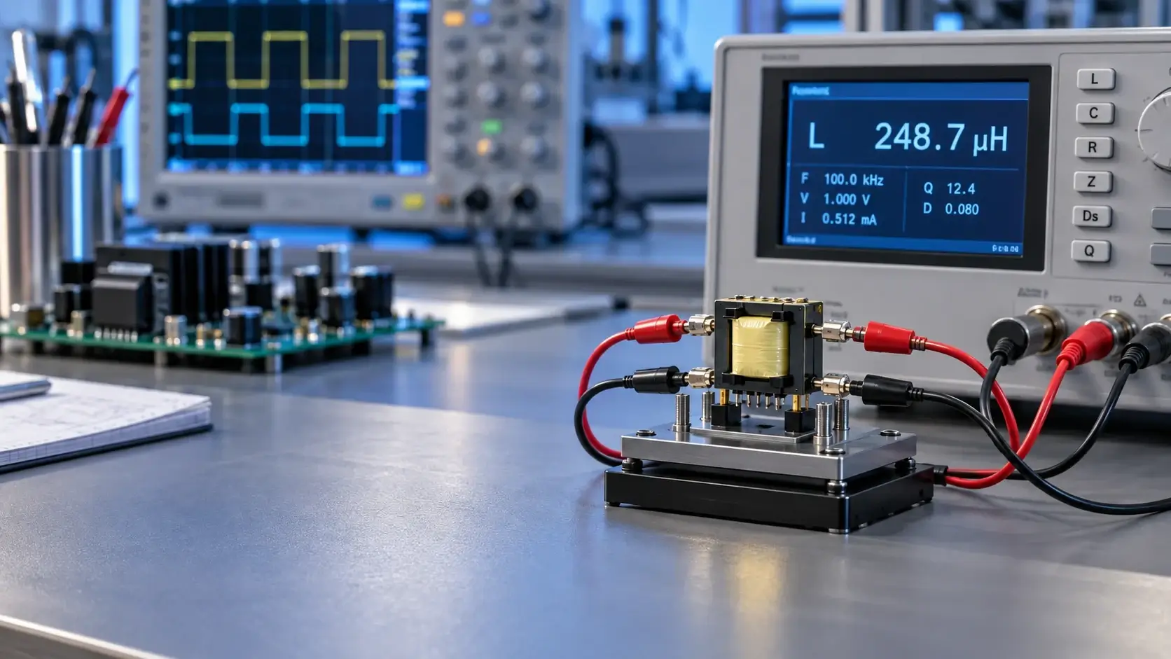
Gate drive transformer values are comparable only when connection, frequency, signal level, and equivalent-circuit mode are the same. Common errors include testing with the wrong secondary condition, using a long shorting lead, or comparing readings taken at different frequencies.
This guide provides a repeatable bench LCR procedure and explains which results support incoming inspection and which must still be verified in the operating gate-drive circuit.
Fix five test conditions before measuring
Record instrument, frequency, AC level, equivalent model, and temperature. Perform open/short compensation with the same fixture and leads used for the test. Gate drive transformer parasitics can be close to fixture parasitics, so uncompensated readings may describe the fixture rather than the part.
| Item | Record | Common error |
|---|---|---|
| Frequency | Datasheet frequency plus a sweep | Reporting a value without frequency |
| AC level | Actual terminal voltage or current | Assuming every meter has the same default |
| Model | Ls/Rs, Lp/Rp, Cs, or Cp | Comparing series and parallel results |
| Compensation | Open and short correction | Changing leads after compensation |
| Temperature | Ambient and stabilization time | Measuring immediately after handling |
Magnetizing inductance: leave other windings open
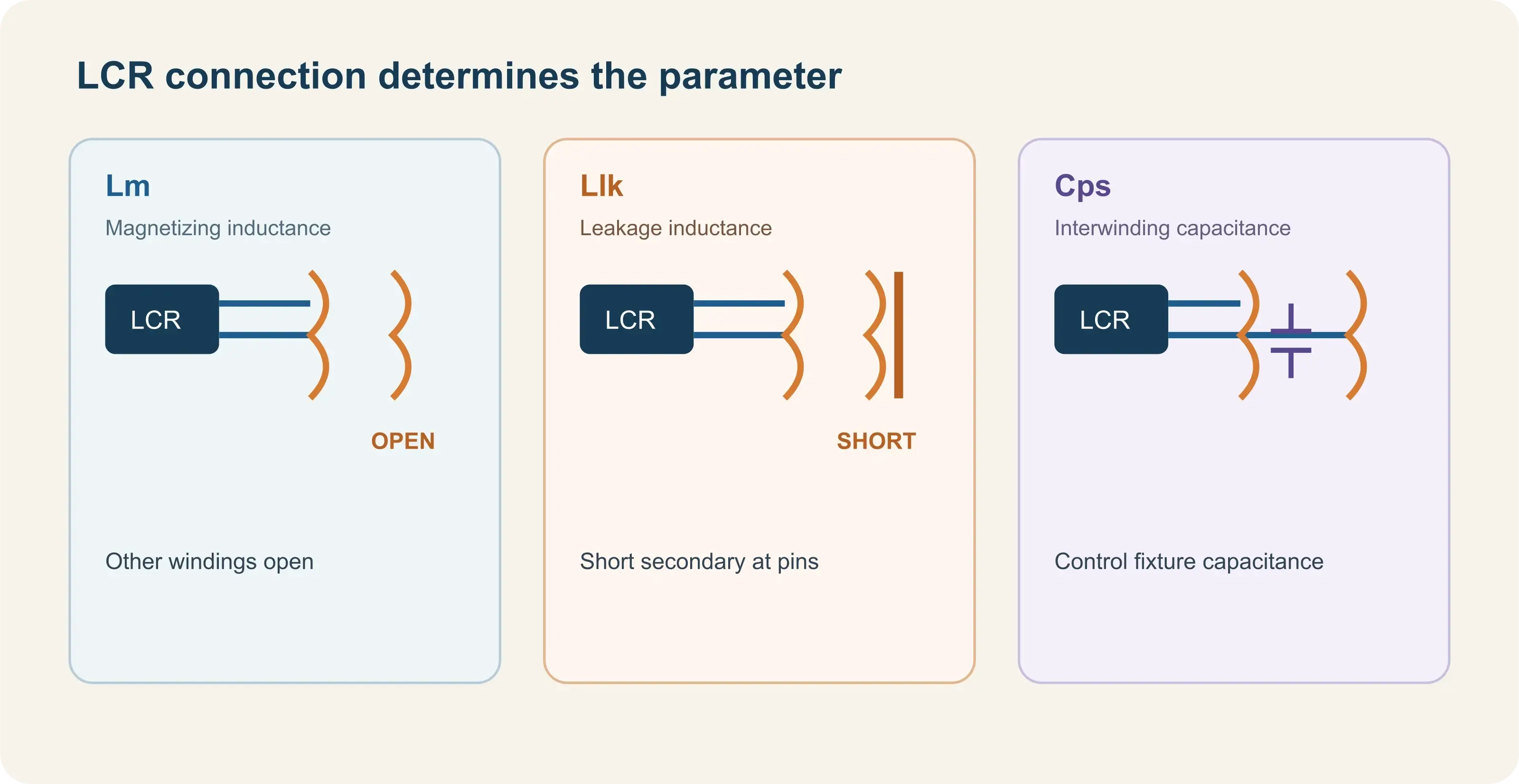
Connect the LCR meter to the selected primary and leave every other winding open. Keysight's transformer guidance specifies open secondary windings for primary or secondary self-inductance measurements. A resistor, oscilloscope, or rectifier connected to the secondary reflects impedance into the primary and changes the result.
Measure at the specified frequency and level, then add a frequency sweep. Frequency-dependent readings do not automatically indicate failure: winding resistance, distributed capacitance, and core loss affect the equivalent model. Supplier and lot comparisons require identical conditions.
Small-signal LCR inductance does not prove volt-second capability because the operating transformer sees rectangular pulses and temperature variation. See the gate drive transformer volt-second balance guide for dynamic reset verification.
Leakage inductance: short the secondary with very low impedance
Short the specified secondary with the lowest practical impedance and measure the residual inductance from the primary. This is the connection shown in the Keysight Impedance Measurement Handbook and its technical support note.
Place a shorting bar directly across the secondary pins. Avoid long clip leads: their inductance adds to the result and can dominate a low leakage-inductance measurement. For multiple secondaries, document which winding is shorted and the state of every other winding.
Why this is not the complete gate-loop inductance
The bench result mainly represents transformer coupling. PCB traces, driver and switch packages, gate resistors, and probing add external inductance. TI notes that tighter or bifilar winding can reduce leakage while increasing primary-to-secondary capacitance. Minimum leakage alone is therefore not a sufficient design target.
Interwinding capacitance: control fixture geometry and shielding
For primary-to-secondary capacitance, connect the terminals of each winding according to the documented method and measure between winding groups. Record the state of unused windings and whether Cs or Cp is used.
Lead spacing, nearby hands, ground planes, and shielding affect picofarad-level results. Keep orientation and wiring fixed and perform open correction. In high-dv/dt SiC or GaN stages, displacement current increases with capacitance and dv/dt, so capacitance must be evaluated with the actual switch-node waveform.
TI's gate drive transformer parasitics article describes the trade-off between lower leakage inductance and higher coupled capacitance in bifilar structures.
Build a repeatable test record
For every sample, retain:
- full part number, sample ID, pinout, and dot orientation;
- LCR meter, fixture, and compensation status;
- frequency, signal level, and Ls/Lp or Cs/Cp model;
- open-winding state for magnetizing-inductance testing;
- shorted winding and shorting-bar construction for leakage testing;
- terminal grouping, shielding, and unused-winding state for capacitance;
- temperature, repeat count, average, and spread.
LCR acceptance still requires dynamic validation
An LCR meter is useful for incoming, lot, and construction comparisons, but it cannot replace operating-waveform testing. Tektronix's in-circuit magnetics note explains that inductance behavior depends on excitation waveform, frequency, voltage, and operating state.
On the power stage, observe driver output, primary current, device gate voltage, and switch-node voltage across startup, steady state, light load, current limit, and fault recovery. If edges slow, ringing grows, or false turn-on appears, use the 1:1 gate drive transformer waveform troubleshooting guide.
Conclusion
Measure magnetizing inductance with all other windings open. Measure leakage inductance from the primary while the specified secondary is shorted with very low impedance. Measure interwinding capacitance only with controlled fixture geometry, terminal grouping, and shielding. Every number needs frequency, signal level, and equivalent model.
For part comparison or replacement review, submit the pinout, test conditions, LCR data, and primary and gate waveforms through the LPEMA contact page. The first step is aligning the measurement method before judging the component.

