
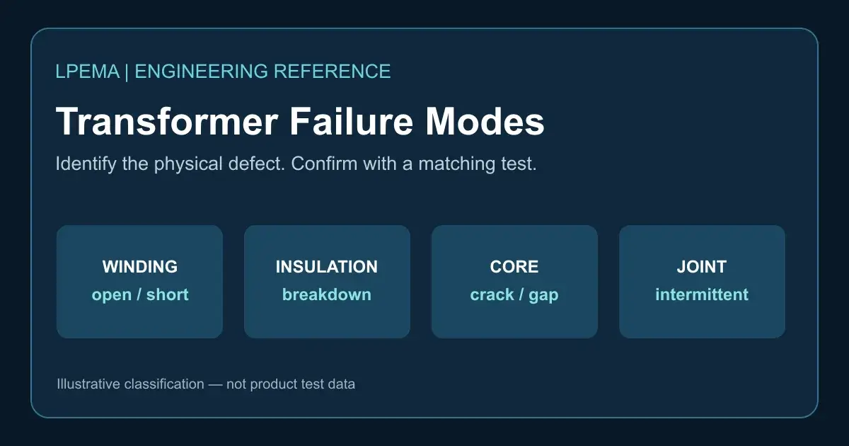
A hot transformer, a noisy converter, or a damaged MOSFET does not by itself prove that the transformer has failed. To identify high-frequency transformer failure modes in compact flyback and gate-drive magnetics, ask: what physical part or electrical property changed, and what evidence confirms it? This guide groups common failure modes by the affected part. It does not rank their frequency: that depends on the design, environment, and production process.
High-frequency transformer failure modes in windings and connections
A broken wire, damaged termination, or cracked solder connection can interrupt a winding or make its resistance unstable. The result may be no output, intermittent startup, or localized heating. Compare continuity and DC resistance with a known-good sample using the same temperature and measurement setup. Inspect the termination and PCB joint before attributing an open circuit to the winding itself. An in-circuit reading can be misleading because parallel components may provide another path.
Shorted turns and winding-to-winding shorts
Damaged wire enamel or insulation can permit a turn-to-turn short. This changes effective turns and may produce excessive circulating current and heating. A primary-to-secondary short is a different and potentially hazardous isolation failure. A normal DC continuity reading alone cannot rule out a shorted turn: compare inductance, loss or impedance, and temperature behavior under controlled conditions. Follow the approved isolation test plan for the specific design; do not apply an arbitrary hipot voltage to an assembled converter.
Insulation breakdown
Insulation can be compromised by mechanical damage, winding crossover, contamination, inadequate spacing, or thermal aging. The symptom may be leakage, arcing, or a failed dielectric test. Check the approved construction drawing, insulation system, and the test voltage, duration, and connection points before interpreting a result. Insulation requirements depend on the actual application and required insulation class; no single voltage applies to every transformer. See Bourns’ magnetic design application note and Würth Elektronik’s power-supply insulation overview.
Core damage, gap shift, and loss of magnetic margin
A cracked core, displaced core half, or changed air gap can alter magnetizing inductance and loss. Separately, a physically intact core may saturate under excessive volt-seconds or peak current; saturation is an operating condition, not necessarily permanent core damage. Compare magnetizing inductance under stated test conditions, inspect the assembly, and check the primary current waveform at the design’s worst-case input and load. A rising current slope needs circuit-level confirmation because current-limit behavior and measurement artifacts can look similar. Coilcraft’s transformer guide discusses saturation and winding temperature limits.
Thermal damage to wire and insulation
Excessive copper or core loss can raise temperature until wire insulation, tape, or bobbin materials deteriorate. Overheating is therefore often a mechanism leading to another failure, not a complete root-cause diagnosis. Record ambient temperature, load, frequency, and stabilized temperature; compare them with the approved material and product limits. Examine whether core loss, DC copper loss, or AC winding loss dominates. Coilcraft’s transformer design note explains winding loss and temperature rise.
Mechanical and assembly failures
Cracked solder joints, damaged pins, a loose core, and displaced insulation can arise during handling, mounting, thermal cycling, or vibration. Check the PCB joint and transformer termination separately. A visual defect is useful evidence, but a final root-cause conclusion should match an electrical or mechanical test.
Failure mode, symptom, and test: a quick comparison
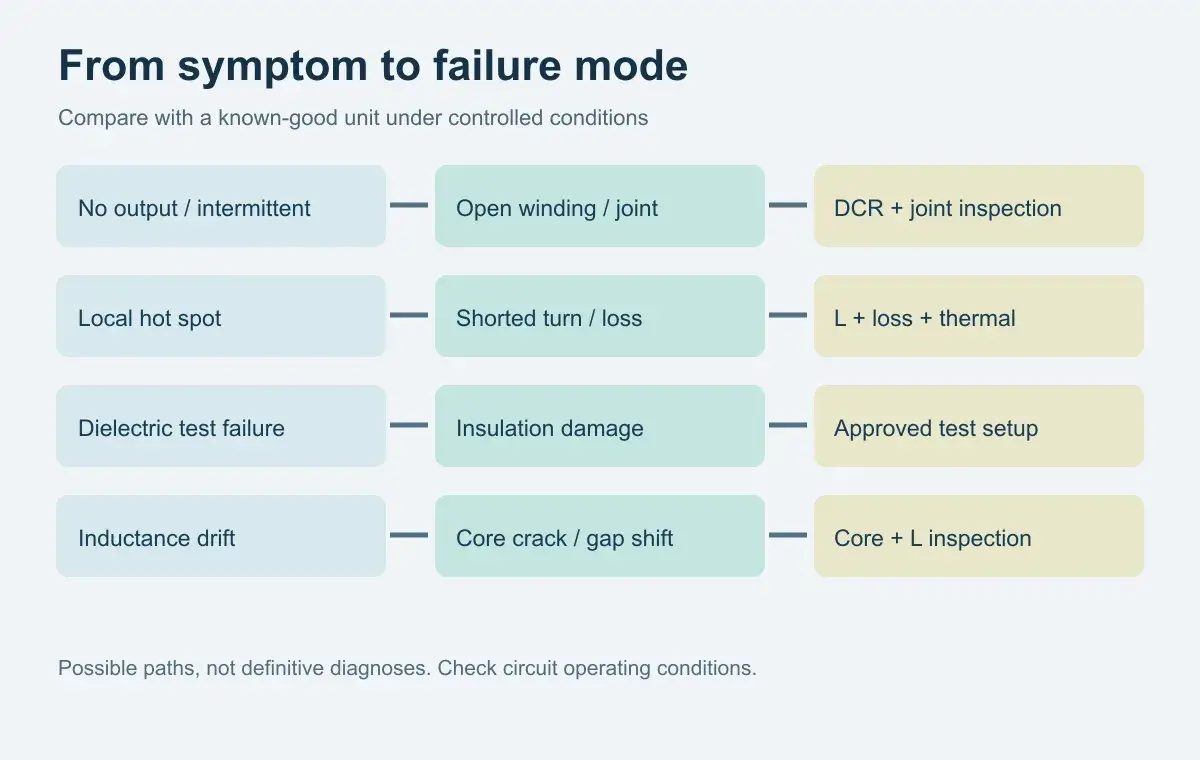
| Observed symptom | Possible failure mode | First confirming checks |
|---|---|---|
| No output or intermittent startup | Open winding or termination | Continuity, DCR, termination and PCB joint inspection |
| Local hot spot or abnormal loss | Shorted turn, high-resistance joint, or excessive operating loss | Impedance/inductance comparison, thermal pattern, operating waveform |
| Failed isolation test | Insulation damage or test/setup mismatch | Approved dielectric procedure, construction and connection review |
| Strong primary-current rise | Core saturation or control-circuit issue | Current waveform, applied volt-seconds, input/load conditions |
| Inductance drift after handling | Core crack or gap shift | Core inspection and controlled inductance comparison |
These are investigation paths, not one-to-one diagnoses. The existing LPEMA troubleshooting guide provides a broader symptom-first workflow; the core saturation diagnostic guide addresses waveform interpretation.
What should an engineer send with a failure report?
Provide the exact part and revision, converter topology, input and load range, switching frequency, failed-unit photographs, a known-good comparison, test setup, and waveforms captured safely. State whether the defect was found at incoming inspection, during production, or after field operation. For a custom compact transformer inquiry, send the electrical and mechanical requirements together with the required test conditions; LPEMA’s specification guide explains the information needed for supplier review.
FAQ
Is overheating itself a transformer failure mode?
It is an observed condition. Determine whether it results from copper loss, core loss, a shorted turn, a resistive connection, or operation beyond the design limits.
Does a sudden primary-current rise prove a damaged core?
No. Saturation can occur in an intact core when the applied volt-seconds or current exceed the design margin. Confirm the circuit conditions and measurement before condemning the component.
Can a DC resistance test detect every shorted turn?
No. A small turn-to-turn short may change DC resistance too little to identify reliably. Controlled inductance and loss comparisons and operating tests may be needed.

