
A 1:1 turns ratio is often the first line in a gate drive transformer specification. It is important, but it describes only the ideal turns relationship. It does not guarantee that the pulse measured at the MOSFET, IGBT, or SiC gate will reproduce the primary waveform.
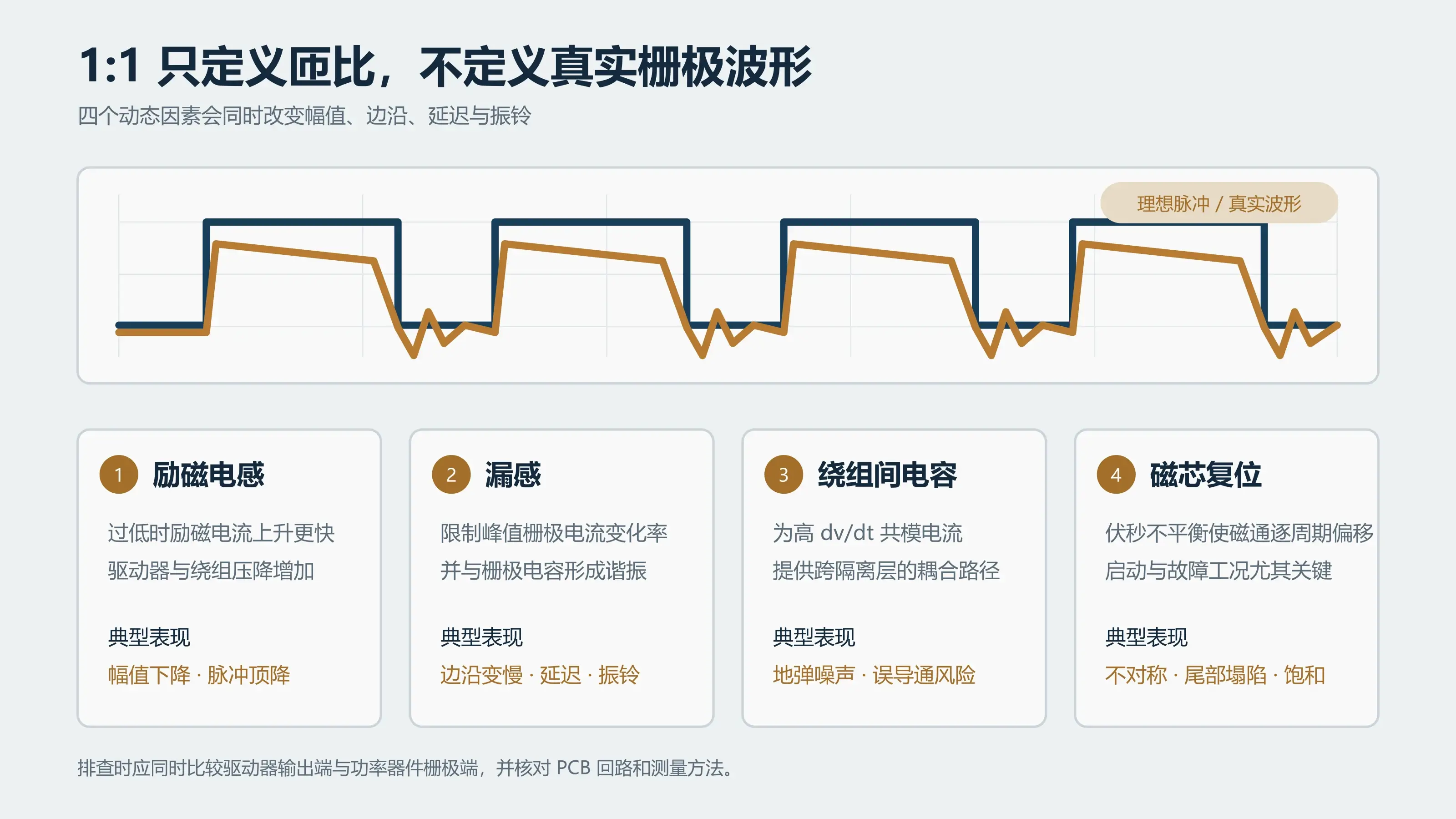
The real gate-drive path includes magnetizing inductance, leakage inductance, winding resistance, interwinding capacitance, external gate resistance, and the gate charge of the power device. Together, these elements determine amplitude, edge speed, propagation delay, droop, and ringing.
A 1:1 ratio is only the starting point
An ideal 1:1 transformer has equal primary and secondary voltages. A power-device gate, however, is not an open-circuit measurement point. It is a capacitive load that must be charged and discharged quickly.
The transformer must deliver high peak current at each transition. Winding and driver resistance create voltage drop. Leakage inductance resists rapid current change. Magnetizing current also consumes part of the driver's available current. A transformer that looks correct at no load can therefore show lower amplitude, slower edges, or pulse-top droop when connected to the real gate circuit.
Four waveform symptoms and what to investigate
Secondary amplitude is lower than expected
Verify the probe connection first. Then check driver source and sink capability, winding resistance, external gate resistance, and the device gate charge. Low magnetizing inductance increases magnetizing current and can add further voltage drop in the driver and winding resistance.
Changing the turns ratio is not automatically the right correction. More secondary turns can also change magnetizing inductance, leakage inductance, capacitance, and the insulation construction.
The pulse top droops
Droop suggests that the drive path cannot maintain the required voltage throughout the pulse. Texas Instruments' gate drive transformer design note relates magnetizing current to drive voltage, on-time, and magnetizing inductance. With lower magnetizing inductance, magnetizing current rises faster during the on-time. Inadequate reset or unequal positive and negative volt-seconds can also move the core flux from cycle to cycle.
Check the longest uninterrupted pulse, not only nominal switching frequency. Startup, burst operation, current limiting, and fault sequences can be more demanding than steady-state operation.
Edges become slower and propagation delay increases
Leakage inductance is in the high-peak-current gate path and limits current slew rate. Infineon's isolated gate-driving application note shows that pulse-transformer leakage inductance directly affects propagation delay and the time needed to charge a power-device gate.
For transformers with multiple secondaries, winding-to-winding delay matching also matters. A mismatch between high-side and low-side drive can reduce effective dead time and increase cross-conduction risk.
Overshoot, ringing, or an off-state gate-voltage rise appears
Leakage inductance and effective gate capacitance form a resonant network. At high switching speed, primary-to-secondary capacitance also conducts common-mode displacement current. If ringing crosses the device threshold, false turn-on can occur.
Minimum leakage inductance is not the only objective. TI's discussion of gate drive transformer parasitics notes that tighter winding coupling can reduce leakage but may increase interwinding capacitance. The final construction has to balance switching speed, common-mode current, insulation spacing, and manufacturing consistency.
Do not isolate the transformer from the rest of the gate loop
A distorted oscilloscope trace is not proof that the transformer alone is responsible. Record and compare:
- Driver-output and device-gate waveforms
- Primary voltage, maximum pulse width, frequency, and duty-cycle range
- Full power-device part number and recommended gate-voltage range
- Gate resistance, clamps, and transformer reset network
- PCB gate-loop area and return path
- Startup, light-load, burst, current-limit, and shutdown behavior
These conditions help separate a transformer mismatch from a gate-loop, layout, or probing problem.
What a useful GDT request for quotation should include
“1:1, 2.5 kV isolation, as small as possible” is not enough for reliable selection. LPEMA's transformer specification and RFQ guide provides a fuller request checklist. At minimum, provide the converter topology, power-device part number, primary pulse conditions, reset method, number of secondary outputs, required gate voltages, gate network, insulation requirements, and mechanical constraints.
LPEMA's current gate drive transformer information covers EP5, EP6, EP7, EFD17, SMD CASE, and ER constructions, including single- and multiple-secondary arrangements. Browse the new energy, PV, and storage magnetics range for the application category, then use the complete gate drive transformer selection guide to check volt-seconds, reset, and insulation. A core family is only a screening parameter; the final choice must be verified against the waveform, gate characteristics, and insulation requirements.
Bottom line
A 1:1 turns ratio defines an ideal voltage relationship. It does not replace dynamic gate-loop analysis.
When the gate waveform loses amplitude, droops, slows down, or rings, evaluate magnetizing inductance, leakage inductance, interwinding capacitance, winding resistance, reset conditions, and the external gate circuit together. The most useful selection input is not a turns ratio by itself, but the real waveform and complete operating conditions.
If you are troubleshooting a gate drive transformer, contact LPEMA with the power-device part number, primary and gate waveform captures, drive timing, isolation requirement, and mechanical limits. We can first evaluate whether an existing construction fits before considering a winding change or custom sample.

