
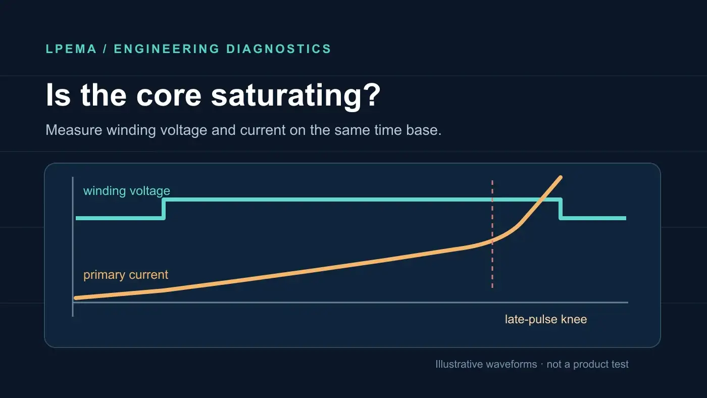
How to detect transformer core saturation is a measurement question, not just a question about whether a transformer feels hot. A rapid rise in primary current near the end of an applied-voltage interval is a useful warning, but the same screen capture can be misleading if the probe, current-sense circuit, or controller changes what you see. The practical answer is to measure voltage and current together, compare several operating states, and verify the suspected loss of incremental inductance.
This guide concerns compact high-frequency power and gate-drive magnetics. The measurement points and magnetic reset conditions differ between a flyback energy-storage transformer and a gate-drive signal transformer; do not apply a flyback current limit to a gate-drive part. For the physical causes and core-material background, see why transformer cores saturate and the B–H curve guide.
How to detect transformer core saturation: the short answer
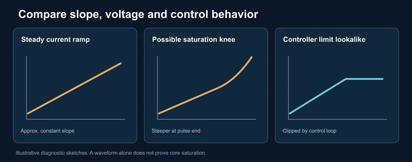
With a suitable isolated or differential voltage probe and a properly rated current measurement, capture the voltage actually across the relevant winding and its current on the same time base. During a switching interval where winding voltage is approximately constant, an unsaturated magnetizing-current component has an approximately steady slope: diₘ/dt ≈ V/Lₘ. If the current slope repeatedly steepens near the end of the interval while winding voltage remains similar, the effective incremental magnetizing inductance may be falling as the core approaches saturation. This is a suspect waveform, not proof by itself. Analog Devices shows a saturated current waveform with a rising slope. Its example concerns an inductor, so apply the diagnostic principle to transformer magnetizing current with the topology and load-current components accounted for.
Step 1: identify which current you are measuring
In a flyback converter, switch-on primary current is closely tied to magnetizing current. In forward, bridge, or other power-transfer topologies, measured primary current also contains reflected load current. In a gate-drive transformer, the driver output current includes gate-charge and parasitic-capacitance current spikes in addition to magnetizing current. The measured current combines these components. Do not assign a change in this combined current to core saturation without checking the circuit.
Record the topology, controller mode, input voltage, load, switching frequency, duty cycle, maximum continuous on-time, core material if known, primary turns, magnetizing inductance, and any stated saturation-current or volt-time limit. Use the actual winding voltage rather than assuming it equals the supply: switch drops, clamp action, and magnetic reset networks change the applied volt-seconds. TI’s flyback magnetics design seminar explicitly calls for currents at the worst operating conditions relevant to saturation, core loss, and winding loss.
Step 2: capture synchronized voltage and current safely
Choose a measurement method that matches the voltage, isolation, bandwidth, and peak current of the circuit. A current probe around a single conductor, a specified current-sense resistor with a suitable differential measurement, or a validated controller sense output may be appropriate. Do not put an earth-referenced oscilloscope ground clip on a floating or live switching node. Minimize probe-loop area, check the current-probe zero and polarity, and keep enough time resolution to see the entire switching interval without mistaking turn-on ringing for a slope change.
Capture startup, steady state, input-voltage limits, load steps, and the longest allowed switching or fault sequence. Save both a single-cycle view and a multi-cycle view. The latter reveals baseline drift or incomplete magnetic reset that a single good-looking cycle can hide. For a gate-drive transformer, our volt-second balance and reset article explains why startup and abnormal switching sequences matter.
Step 3: look for a repeatable current-slope increase near the end of the interval
Compare the current slope in the middle and near the end of the same constant-voltage interval. A repeated, pronounced upward bend near the end is stronger evidence than a high current peak alone. Check whether the bend moves earlier when on-time or applied voltage increases, and whether it recedes when volt-seconds are reduced under a controlled test. Keep the test within the converter’s and probe’s safe limits; do not deliberately force an unknown transformer into damaging saturation.
For a flyback design, compare measured peak primary current with the transformer specification using the manufacturer’s definition and test condition for saturation current. A generic saturation-current number is not a universal trip point: temperature, inductance-drop criterion, and measurement conditions matter. Bourns relates primary inductance, peak current, turns, core area, and saturation flux density in an application note on flyback power supplies (listed under Technical sources below). No such calculation can establish an LPEMA part’s limit without its verified winding and core data.
Step 4: check volt-seconds and magnetic reset
Integrate the measured winding voltage over the applied interval. If that voltage is roughly constant, the change in flux density is approximately ΔB = V × t ÷ (N × Aₑ).
- N means the number of turns in the measured winding.
- Aₑ means the effective cross-sectional area of the magnetic core.
- V is the approximate voltage across that winding during the interval.
- t is the duration of that interval.
Use the voltage across that winding, not just the bus voltage. A full-cycle integral that does not return toward the expected magnetic reset condition can suggest flux walk, but winding resistance, probe offset, and integration drift must be checked before interpreting it. TI explains that positive and negative volt-time products across the winding must balance to avoid saturation.
The equation calculates a change in flux density. It does not calculate the absolute flux density inside the magnetic core. Initial flux, DC bias, remanence, air gap, temperature, and material data determine the remaining margin. A gate-drive transformer may have a usable volt-time rating; TI’s gate-drive transformer note explains why a DC-blocking capacitor can force average transformer current toward zero and avoid saturation. A flyback transformer’s peak-current and energy-storage checks are different.
Step 5: rule out other causes before concluding that the magnetic core is saturated
| Observation | Other plausible cause | Next check |
|---|---|---|
| A sharp current spike exactly at turn-on | Capacitive charging, reverse recovery, noise picked up by the probe, or leakage-inductance ringing | Inspect after the transient settles; reduce the probe loop and compare switch voltage |
| A flat-topped or clipped measured current signal | Controller current limit, amplifier saturation, or oscilloscope input range | Compare raw current-sense resistor voltage, gate-drive command, and probe range |
| Current rises throughout the switching interval | Normal magnetizing-current ramp or reflected load-current change | Compare slope at approximately constant winding voltage, not peak alone |
| One abnormal startup cycle | Inrush current, remanent magnetization in the magnetic core, or the startup control sequence | Compare repeated starts and steady-state cycles; inspect magnetic reset |
| Gate waveform droops while driver current rises | Driver output resistance, gate load, magnetizing inductance below the design requirement, or core saturation | Measure driver supply, gate load, winding voltage, and current together |
This differential diagnosis matters because replacing a transformer on the basis of a single distorted trace can leave the actual fault in the controller, gate loop, or measurement setup. A repeatable increase in current slope, a plausible volt-second mechanism, and consistent behavior across controlled operating changes make the diagnosis stronger.
Information to provide for a magnetic design review
For a high-frequency transformer or gate-drive transformer review, share the circuit topology, winding-voltage and current captures with scale and probe details, input and load range, switching frequency, longest on-time or duty cycle, magnetic reset scheme, operating temperature, winding turns and magnetizing inductance if available, and the part’s drawing or specification. That evidence lets a manufacturer assess whether the magnetic design fits the waveform; a photograph of a hot component does not establish core saturation.
LPEMA reviews specifications for compact high-frequency magnetics. Prepare the topology, operating range, measured waveforms, and required dimensions before requesting a design review. Final suitability depends on a verified design and prototype tests; this article does not assign a saturation-current, core material, or certification to any LPEMA model.
Read the guide to preparing custom transformer specifications before submitting the requirements.
Send the measured waveforms and requirements through the LPEMA engineering contact page.
FAQ
Can a multimeter tell me whether a transformer core is saturated?
Usually not in a switching converter. A DC resistance reading does not show how incremental inductance changes during a switching interval. Use an appropriate voltage/current waveform measurement and the part’s relevant magnetic specification.
Can a high peak in primary current prove that the magnetic core is saturated?
No. A high current peak can occur under load or during startup. Look for a repeatable current-slope change under similar winding voltage, then check magnetic reset and compare with a verified part specification.
Why might saturation appear only when the circuit is hot?
Core properties and circuit operating conditions change with temperature. Repeat the waveform and specification check at the actual worst-case temperature; do not infer a universal temperature derating from a different ferrite material.
Is gate-drive transformer saturation diagnosed exactly like flyback saturation?
No. Both require voltage and current context, but a gate-drive transformer carries switching signals and needs magnetic reset, while a flyback transformer stores energy in magnetizing inductance. Their load-current components and relevant limits differ.
Technical sources
- Texas Instruments, Magnetics Design 5: Inductor and Flyback Transformer Design
- Texas Instruments, volt-time balance in flyback waveforms
- Texas Instruments, gate-drive transformer saturation and reset
- Analog Devices, example of an inductor saturation current waveform
- Bourns, Designing a Low Power Flyback Power Supply

