
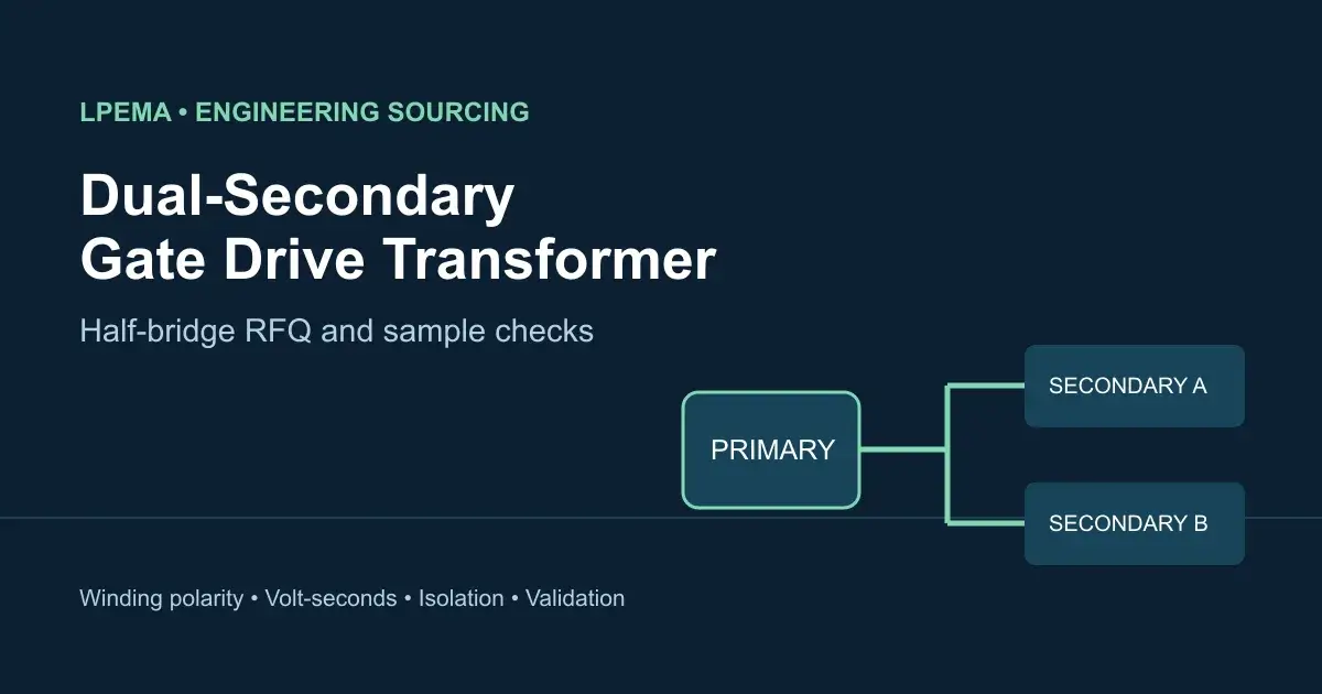
A dual-secondary gate drive transformer can transfer two isolated gate-drive waveforms from one primary-side drive circuit. In a half-bridge, the two power switches operate at different electrical potentials, so each secondary needs its own correctly referenced gate circuit. The part is a candidate only when its winding arrangement, waveform capability, insulation and mechanical drawing match the actual design.
Where a dual-secondary gate drive transformer fits
A gate drive transformer transfers a time-varying drive signal. It cannot by itself provide a regulated, continuous isolated bias rail. Confirm the intended architecture before requesting a part: transformer-coupled gate drive and an isolated gate-driver IC with a separate bias transformer require different magnetic specifications. Our gate drive transformer versus digital isolator guide explains that distinction.
Würth Elektronik lists gate drive transformer families with one or two secondaries, including a 1:1:1 option in its WE-GDT range. This establishes that the winding configuration is a real catalog selection criterion; it does not establish interchangeability with an LPEMA part. The LPEMA product catalog includes EP5 gate-drive entries with two secondary windings. Request the controlled LPEMA drawing and datasheet for the exact candidate before treating any catalog row as a purchase specification.
RFQ inputs for a half-bridge gate drive transformer
| Send the supplier | Why it matters |
|---|---|
| Primary drive waveform, voltage, frequency, maximum on-time and reset interval | Determines the worst-case applied volt-seconds and whether the core can reset |
| Required secondary gate voltage and gate-charge demand for each switch | Establishes turns ratio and transient-current needs without assuming the two channels have identical loads |
| Switch type, gate-driver circuit and turn-on/turn-off resistor network | Defines the voltage waveform at each transistor gate and its damping conditions |
| Winding schematic, dot polarity and each secondary’s reference node | Prevents an apparently correct ratio from driving a switch with the wrong polarity or reference |
| Required working voltage, transients and end-equipment insulation standard | Allows construction and spacing to be reviewed separately from a one-time dielectric test |
| PCB pad layout, height limit, pin map, assembly process and annual quantity | Makes the commercial quote relevant to the intended PCB and production process |
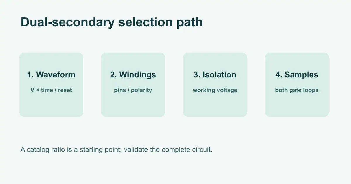
For the magnetic check, calculate the maximum primary voltage-time integral over the actual drive waveform, including abnormal duty conditions. Texas Instruments’ gate-driver design guide discusses the volt-second limit and transformer reset in gate-drive circuits. A nominal 1:1:1 turns ratio alone cannot establish saturation margin.
Compare the two output windings separately
Ask for a drawing that identifies every terminal and polarity dot. For a MOSFET, measure each gate voltage relative to that MOSFET’s source terminal; for an IGBT, use its emitter terminal. Do not use a shared oscilloscope ground as the gate-voltage reference. Include suitable isolated or differential measurement methods in the test plan. The upper and lower gate loops can differ in routing, parasitic capacitance and loading even when the windings have the same nominal turns.
Specify how primary inductance, leakage inductance and winding capacitance will be measured. Test frequency, level, fixture and which other windings are shorted or left open must accompany each value. The LPEMA waveform distortion article explains why turns ratio alone does not predict the voltage waveform at the transistor gate. Evaluate inter-channel timing and dead time in the complete half-bridge test; this sourcing guide focuses on what to put in the RFQ and sample acceptance plan.
What to request with samples
Request the current approved datasheet, winding and pin drawing, documents describing the insulation structure, test limits and a clear drawing revision. Evaluate both secondary waveforms at the intended line, load, temperature and duty conditions. Check reset at the longest allowed on-time, gate-voltage limits, ringing, turn-off behavior, inter-channel timing and temperature rise. Review the complete gate circuit and switch datasheets when setting acceptance limits.
If a buyer has a competitor part number, send its datasheet as a comparison reference. A replacement conclusion needs a line-by-line check of winding function, pins, polarity, volt-seconds, parasitics, insulation, mechanical fit and prototype results. A shared core shape or ratio is insufficient.
FAQ
Can one dual-secondary transformer drive both switches in every half-bridge?
No. The drive method, maximum duty cycle, reset path, required gate voltage, isolation and fault behavior must all fit the circuit. Review those conditions before choosing a winding arrangement.
Is 1:1:1 enough information to order samples?
No. It describes a nominal winding relationship. Supply the actual drive waveform, winding references, insulation requirement, footprint and sample test criteria.
Is a hipot number the continuous working voltage?
No. A dielectric test and a continuous working-voltage claim answer different questions. Specify the end-equipment insulation requirement and request the supporting construction documentation.
What should I send LPEMA first?
Send the schematic, gate-driver and switch part numbers, primary waveform, secondary references, PCB constraints, insulation targets and expected volume. Use the LPEMA gate drive transformer selection guide to organize electrical checks, review the LPEMA transformer product category for initial options, then contact LPEMA for an approved engineering drawing and sample discussion.
Sourcing decision
The right dual-secondary gate drive transformer is the one whose documented winding arrangement and verified sample waveforms fit the half-bridge. Treat catalog entries as a shortlist, then close the electrical, insulation and mechanical questions before placing a production order.

