
EFD Transformer Selection for Low-Profile Power Supplies
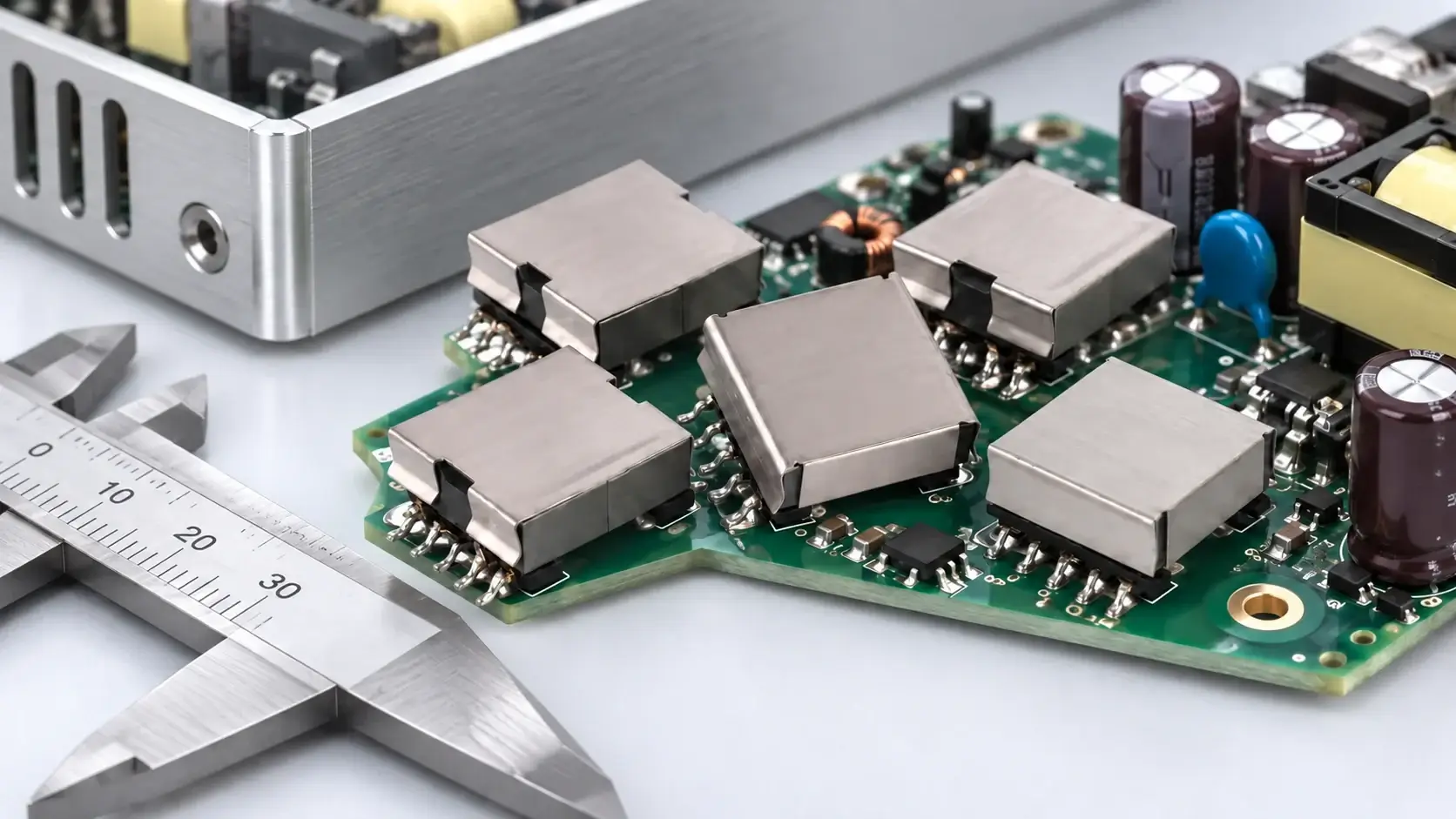
When a power supply has a strict height limit, an EFD transformer is often shortlisted for its flat core profile. But the core shape alone does not tell you whether a proposed part will meet the converter's electrical, thermal, insulation, and assembly requirements. A sound EFD transformer selection starts with the finished mechanical envelope and the actual converter operating conditions, then verifies the winding and test requirements against a controlled drawing.
Why engineers shortlist EFD transformers for low-profile designs
EFD core geometry is intended for a flatter transformer package. Coilcraft's general switching-transformer design note identifies EFD as its lowest-profile option among the compared EP and EFD cores. That is useful for an initial shortlist, not a guarantee that every EFD construction is lower than every competing part: bobbin, winding build, insulation, terminals, core clips, and the supplier's complete assembly drawing determine the finished height. TDK's EFD/EV core and accessory catalog lists individual geometry and material variants.
For LPEMA designs, use the EFD transformer product range to identify relevant package families, then request the current drawing and electrical specification for the specific part number under review. The catalog family name is a starting point; verify dimensions and winding details for the exact part number and revision.
1. Define the real height and footprint limit
Write down the maximum assembled height from the PCB surface to the enclosure, including the permitted tolerance. Confirm whether the limit includes solder joints, component keep-outs, board flex, airflow clearance, or an insulating barrier. Check the board footprint and pin locations against the actual land pattern, not a core outline alone.
Compare the proposed part drawing with the enclosure and adjacent components. A low-profile transformer can still fail mechanically if its pins, mounting features, insulation margins, or assembly tolerances conflict with the board or cover. If the design allows several core families, compare complete part outlines and winding windows rather than comparing only the core names.
2. Match the transformer to the converter operating envelope
Provide the transformer supplier with the topology and controller, minimum and maximum input, switching-frequency range, duty-cycle limits, output rails and load combinations, startup behavior, and relevant fault conditions. These values establish the electrical conditions the transformer must support.
For a switching transformer, the applied voltage waveform and on-time determine the volt-seconds applied to the primary. The core and winding design must be checked against the worst operating corner and the selected core material's behavior at the intended frequency and temperature. Do not infer a usable power rating from an EFD size label: power capability depends on the full design, including waveform, frequency, core material, winding, allowable temperature rise, and cooling.
The Coilcraft structured design note lays out a calculation-led process and distinguishes core geometry from the electrical design. Its example values describe that reference design and should not be treated as ratings for LPEMA products.
3. Check winding space, losses, and temperature together
The bobbin window must accommodate the turns, conductor size, insulation system, and winding arrangement while remaining manufacturable. More turns or thicker insulation can increase winding build; changing conductor size or layer arrangement can affect copper loss, leakage inductance, and thermal behavior. These trade-offs should be reviewed against the candidate's drawing and measured specification rather than assumed from a photograph.
Ask how primary inductance, leakage inductance, and winding DCR are specified and measured, including frequency, signal level, shorted-winding condition, and temperature where applicable. Compare candidates only when the methods and conditions match. Then validate the selected transformer in the actual converter at the operating corners that create the greatest electrical and thermal stress.
4. Treat isolation and pin mapping as design requirements
State the end-equipment insulation requirement, working voltage, required insulation construction, and applicable product standard for the application. Confirm these against the exact drawing and documentation. A core family or catalog category does not by itself establish a safety approval or certify the complete power supply.
Verify winding-to-pin mapping, polarity, creepage and clearance in the assembled design, and the PCB land pattern. For multi-output parts, identify each winding and its load range. LPEMA's EFD17 multi-output flyback article explains why pin mapping and winding polarity need to be checked at integration time; it is a separate application example, not a specification for every EFD transformer.
5. Compare catalog parts and custom requirements fairly
Use a catalog part when its documented electrical and mechanical characteristics match the design and the supplier can provide the relevant controlled documentation. If the proposed part misses a height, footprint, pinout, winding, or insulation requirement, provide the supplier with a specification package before requesting a custom proposal. The custom transformer specification guide can help organize those inputs.
| Selection item | What to confirm | Evidence to request |
|---|---|---|
| Package | Maximum assembled height, footprint, pin map, tolerances | Controlled outline drawing and land pattern |
| Electrical design | Topology, input/output conditions, frequency and duty range | Electrical specification tied to the exact part revision |
| Magnetics | Inductance, leakage, turns ratio and test conditions | Test method, fixture conditions and acceptance limits |
| Thermal | Ambient, airflow, loading and temperature limits | Application-specific sample test plan and results |
| Insulation | End-equipment requirement and winding construction | Construction details and applicable compliance documents |
| Production | Winding arrangement, termination and revision control | Approved drawing and change-control agreement |
Do not call a visually similar part a drop-in replacement. Compare the controlled drawings and specifications item by item, then validate samples in the target circuit. This is especially important when a package family contains several winding options or customer-specific constructions.
EFD transformer selection checklist
- Set the maximum assembled height and PCB footprint, including tolerances and keep-outs.
- Document topology, input range, switching conditions, outputs, load combinations, and fault cases.
- Confirm the exact part number, drawing revision, pin mapping, and winding polarity.
- Agree on inductance, leakage, DCR, and turns-ratio measurement conditions.
- State the insulation and end-equipment requirements; do not infer certification from core shape.
- Evaluate temperature and converter behavior using samples in the intended design.
- Record the approved part revision and acceptance criteria before production release.
Frequently asked questions
Does an EFD transformer automatically fit a low-profile power supply?
No. EFD is a low-profile core geometry, but the completed transformer height depends on its core, bobbin, winding, insulation, and terminals. Verify the outline drawing against the enclosure and PCB.
Can I choose an EFD transformer by output power alone?
No. Power capability depends on the topology, voltage waveform, switching conditions, core material, winding losses, cooling, and allowed temperature. Confirm the design with the supplier's exact specification and application testing.
Are EFD15, EFD17, or EFD20 ratings universal across manufacturers?
No. These designations identify geometry families, not universal electrical ratings or interchangeable pinouts. Compare the exact part drawing and test specification.
What should I send LPEMA for an EFD transformer review?
Send the schematic or topology, input and output conditions, controller and switching range, PCB outline and height limit, insulation requirements, and the target measurements or acceptance criteria. Contact LPEMA to discuss a specific part number or a custom design.
Choose the complete part, not just the core shape
EFD geometry can help solve a height constraint, but the final choice must also meet the converter's electrical, thermal, insulation, footprint, and manufacturing requirements. Start with the LPEMA EFD transformer range, then verify a specific part number and drawing with the application conditions before committing to samples or production.

Please Contact Us
