
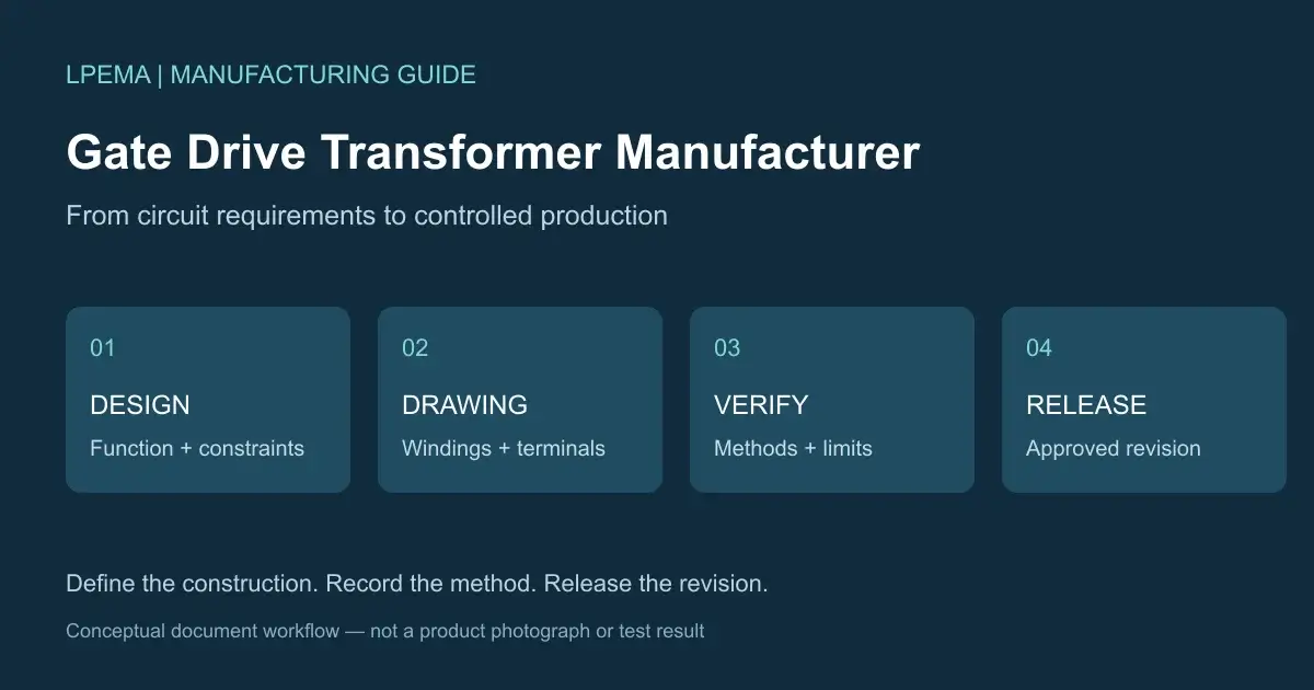
A custom gate drive transformer begins with an electrical requirement, but successful production depends on how clearly that requirement is translated into a physical component. Working with a gate drive transformer manufacturer means agreeing on the drawing, construction requirements, measurable limits, and release process that define the finished part.
For a compact SMD or SMT project, the LPEMA EP transformer product family provides a starting point for discussing package options. A catalog entry is an initial reference: the intended pulse-transfer or isolated-power function, winding arrangement, and insulation requirements still need to be confirmed for the application. This guide follows that design into manufacturing documents and production acceptance.
What a gate drive transformer manufacturer must translate into production
A circuit specification describes what the transformer needs to do. Manufacturing documents describe how to build and verify it. For example, a circuit may require two secondary windings with a particular voltage relationship. The drawing must also identify their terminal numbers, polarity, insulation boundaries, and connection sequence.
| Design area | Production information to define |
|---|---|
| Electrical function | Winding arrangement, turns ratio, polarity, and specified electrical limits |
| Physical construction | Core and bobbin references, wire requirements, winding sequence, and insulation arrangement |
| PCB interface | Package dimensions, terminal numbering, pitch, mounting orientation, and land-pattern reference where available |
| Verification | Test connections, conditions, acceptance limits, and inspection records |
The objective is to make the approved construction reproducible and its acceptance criteria unambiguous. These are proposed project deliverables, rather than claims that every listed document is available for every LPEMA catalog part.
1. Establish the transformer’s function before defining its construction
A pulse gate drive transformer transfers the control waveform across an isolation barrier. A transformer supplying isolated power to a gate driver serves a different function. These roles require different inputs and should be identified at the start of the project. Würth Elektronik distinguishes its WE-GDT pulse transformer family from its auxiliary gate drive transformer family.
For pulse transfer, review the applied winding voltage, pulse duration, operating frequency, duty-cycle range, and reset conditions. For a gate-driver power supply, also establish the converter topology, input range, output requirements, and regulation arrangement. Label the intended function on the application brief and drawing.
For electrical selection fundamentals, use the Gate Drive Transformer Selection Guide for SiC, IGBT, and MOSFET Designs.
2. Convert the winding concept into an unambiguous drawing
A winding diagram needs to show more than a ratio such as 1:1:1. Identify every winding’s terminal numbers, polarity marks, electrical connections, and unused terminals. State whether the terminal layout is viewed from above or from the solder side.
The mechanical drawing and winding diagram should use the same numbering convention. Before sample approval, compare both with the schematic and PCB footprint. For multiple secondary windings, confirm which insulation requirements apply between each winding pair. Primary-to-secondary requirements do not automatically define secondary-to-secondary requirements.
Drawings in the Bourns isolation transformer brochure illustrate why winding arrangements and insulation descriptions belong with the electrical specification. They are reference examples, not evidence of interchangeability with an LPEMA part.
3. Document the winding arrangement that produced the approved sample
Electrical performance depends partly on physical construction. Changing winding positions can affect leakage inductance and interwinding capacitance. Increasing separation for insulation can also change coupling and the space available for copper. The winding design involves trade-offs, as discussed in VAC’s gate drive transformer guidance.
Manufacturing instructions may need to control the winding sequence, wire type, insulation layers, lead routing, and termination method. The required detail depends on which features influence the approved performance and insulation design. Where variation is permitted, define an acceptable range. Where a construction detail is critical, identify it explicitly.
Ask whether another qualified operator could reproduce the approved construction using the released documents. If the answer depends on an explanation from the prototype builder, improve the documentation before release.
4. Connect insulation requirements to the actual construction
An insulation requirement must be translated into materials, dimensions, and assembly instructions. A dielectric withstand test is one verification step. Its result alone does not establish continuous working voltage or prove compliance of the complete end product.
Establish the required insulation level, working conditions, and applicable standard. Then review the proposed construction and supporting evidence. Depending on the design, controlled details may include wire insulation, barrier materials, winding separation, terminal spacing, and relevant creepage and clearance dimensions.
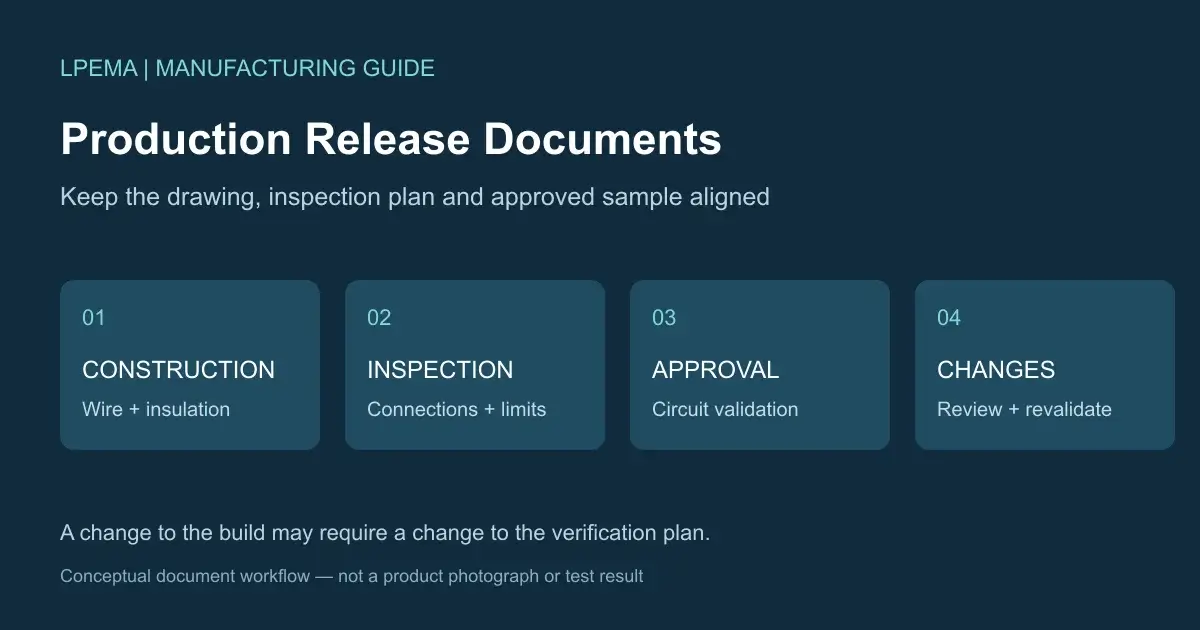
Keep the specification, drawing, and inspection plan consistent. A change to wire, bobbin geometry, or winding placement may require another insulation review even when the nominal ratio remains the same. Manufacturer datasheets distinguish these characteristics: the Bourns isolation transformer brochure separately identifies insulation arrangements and electrical test ratings.
5. Define electrical limits together with their test methods
A numerical limit can cause disagreement if its measurement connections and conditions are undefined. The acceptance specification should identify how each controlled characteristic will be verified.
| Parameter | Details to agree before production |
|---|---|
| Turns ratio and polarity | Terminal connections, winding identification, and acceptance criteria |
| Magnetizing inductance | Winding measured, frequency, excitation level, and condition of other windings |
| Leakage inductance | Measurement winding, shorted winding connections, fixture, and test conditions |
| DC resistance | Winding terminals, method, and temperature reference where relevant |
| Interwinding capacitance | Winding groups, terminal connections, and test conditions |
| Dielectric withstand | Test points, voltage type, duration, and acceptance criteria |
Agree which checks apply to every unit, sampled units, and qualification or periodic verification. Each production test should detect a defined defect or confirm a specified characteristic. Coilcraft’s measurement guidance explains why measurement frequency and instrumentation influence reported inductance. It supports specifying the method; it does not prescribe a universal test frequency for this transformer.
6. Separate component acceptance from circuit validation
Component inspection confirms that the part matches its drawing and electrical limits. Circuit validation establishes performance with the actual driver, power device, gate resistance, PCB layout, and operating conditions.
For pulse drive, evaluate the relevant gate waveform, pulse droop, ringing, reset behavior, and operating limits. Record the conditions used for approval. A sample accepted at nominal voltage and room temperature has not established performance across untested conditions.
When circuit testing requires a design change, revise the specification and construction documents together. This prevents the next batch from being built to an earlier design.
7. Release an approved revision for production
Prototype approval should lead to a specific document revision. The release package should identify the approved drawing, electrical specification, inspection requirements, and any agreed reference samples. Where relevant, define marking, packaging, and traceability requirements.
For compact SMT components, terminal condition, package orientation, and packaging format should suit the assembly process. Confirm that the quotation, purchase order, and released drawing refer to the same revision, particularly when several prototypes look alike.
A practical release record connects each approved document to its revision and approval date. It should also identify open items. Do not silently treat a pending insulation review or incomplete circuit test as a completed approval.
8. Review changes that could affect the approved design
Changes to core material, wire, insulation, winding arrangement, adhesive, or termination process may require review even when external dimensions remain the same. The required revalidation depends on the change and the characteristics it could affect.
Agree when customer notification is required, which documents must change, and what evidence is needed for approval. Record the affected part and revision so future orders can identify the correct construction.
For example, a proposed wire substitution should be reviewed against its insulation system, diameter, resistance, termination process, and winding fit as applicable. Whether a repeat test is necessary depends on that review. A matching nominal conductor size alone does not close the change.
Applying this process to an LPEMA sourcing project
Start with the available drawing for a candidate in the LPEMA EP transformer family. Identify the dimensions and characteristics that suit the application, then list the items needing confirmation or modification. These may include the function, winding configuration, pin assignment, insulation arrangement, or measurement conditions.
An existing package narrows the mechanical options. Application suitability still needs to be established against the agreed specification and sample evaluation. For comparing proposals before sampling, read SMD Gate Drive Transformer Supplier: 10 Checks Before You Order Samples.
Frequently asked questions
Is a turns ratio enough to manufacture a custom gate drive transformer?
No. The design package also needs winding connections, polarity, operating conditions, insulation requirements, mechanical constraints, and electrical acceptance limits.
Why can transformers with the same ratio behave differently?
Different cores, winding arrangements, wire, and insulation structures can change inductance, capacitance, resistance, and waveform transfer.
Should every electrical parameter be tested on every unit?
Define the inspection plan around the specification, manufacturing risks, and agreed quality requirements. Some checks may apply to every unit; others may be sampled or performed during qualification.
Does passing a hipot test prove reinforced insulation?
A hipot result alone does not prove reinforced insulation. Assess the construction, materials, working conditions, and applicable standard together.
Can an existing package be used for a custom winding?
It may be possible following engineering review. Available winding space, insulation requirements, terminal layout, and electrical performance can limit the designs that fit.
Discuss your design with LPEMA
Contact LPEMA with your reference datasheet or drawing, transformer function, waveform, mechanical limits, and insulation requirements. Include available sample results or known design issues. These inputs help frame the review around the construction, documents, and acceptance criteria needed for your project.

