
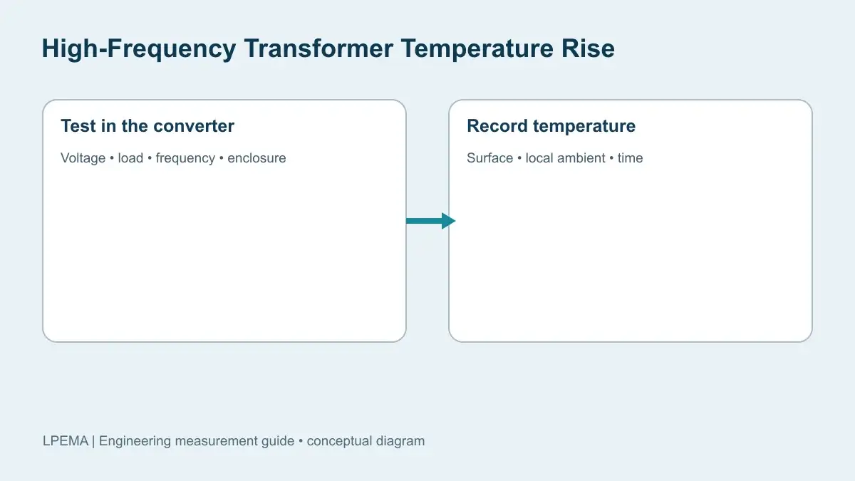
High-frequency transformer temperature rise measurement should take place in the intended converter and environment. A room-temperature DC resistance reading or a no-load bench run cannot establish the winding and core temperatures at the worst operating point. Core and winding losses vary with waveform, switching frequency, load, cooling and surrounding heat sources. Coilcraft technical guidance explains why small-signal ESR can miss large-signal magnetic losses and why measurements under operating requirements matter.
What should a high-frequency transformer temperature rise measurement report?
Report both the observed temperature and its reference conditions. Temperature rise is the measured location temperature minus the local ambient temperature at the same time. It is not interchangeable with absolute part temperature. Record the probe position, local ambient location, converter enclosure, airflow, PCB orientation, nearby heat sources, measurement method, calibration and measurement uncertainty. A thermal camera image is useful for finding accessible hot areas, but emissivity and reflections affect its reading; use a suitable surface treatment or corroborating contact probe where appropriate. Neither surface method automatically reveals the temperature of an internal winding hot spot.
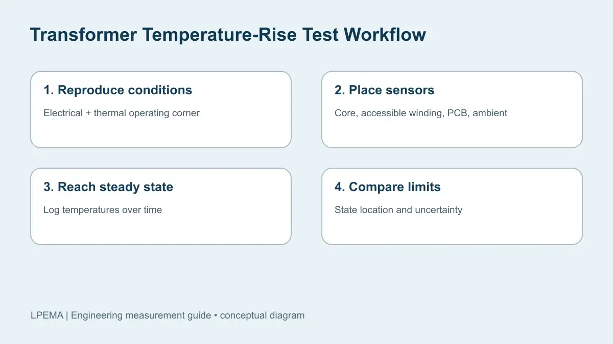
Reproduce the electrical and thermal operating window
Define the actual input-voltage range, output load, switching-frequency range, control mode, duty-cycle behavior and startup or fault conditions that the product must tolerate. Measure at combinations likely to maximize core flux and RMS winding current, then repeat at the highest specified ambient and in the intended enclosure or airflow arrangement. Avoid claiming that maximum output power alone is always the hottest condition: light load, high line or a mode change can alter core excitation and cooling. Würth Elektronik’s isolated buck application note explains that a DC current rating does not include all AC self-heating in a switching transformer.
Wait until the assembly is thermally stable under each steady operating condition. Record temperature over time rather than taking a single reading immediately after energizing. Define the stability criterion before testing, then document the duration and final trend. Transient startup and fault tests need their own time-resolved observations; do not combine their peaks with a steady-state rise figure.
A useful test record has one row per specified operating condition:
| Condition | Record | Why it matters |
|---|---|---|
| Input and load | Voltage, output current, control mode | Defines the actual electrical stress |
| Switching behavior | Frequency, duty cycle, winding voltage and current | Helps interpret core and copper heating |
| Thermal environment | Ambient probe, enclosure, airflow, board orientation | Makes the rise reproducible |
| Temperature | Sensor locations, time series, final trend | Separates transients from steady state |
Where should sensors go on a compact SMD transformer?
Check accessible core surfaces, exposed winding or termination locations where safe, and nearby PCB areas. Keep temperature sensors electrically insulated and mechanically secured so they do not bridge pins, disturb airflow or substantially change heat flow. If the winding is inaccessible, state that its internal hot-spot temperature remains unknown. A prototype with an embedded sensor or an appropriately validated resistance-based method may be necessary for a project-specific winding limit. Do not infer the winding limit from an attractive thermal image of the core.
For a before-and-after comparison, use the same board, operating point, probe positions and ambient conditions. Record input and output electrical measurements as context; total converter loss is not transformer loss alone. Coilcraft’s switching power transformer design guide relates winding loss to transformer temperature rise,.
Interpret a hot transformer without over-diagnosing it
A hot surface establishes a thermal observation, not the root cause. Compare the measured voltage waveform, primary current waveform, load, switching frequency and local ambient with the intended design. Core excitation, skin and proximity effects, leakage-related circuit losses, nearby semiconductors and airflow can each contribute. If current rises disproportionately within a pulse, use the current-waveform saturation diagnostic to investigate; temperature alone does not prove saturation. The failure-modes reference separates observed symptoms from physical failure mechanisms. For a low-profile build, the EFD selection guide shows why mechanical envelope and operating conditions must be evaluated together.
What belongs in a supplier test request?
Specify the converter topology and board revision, input and load matrix, switching-frequency range, enclosure, airflow, ambient range, allowable temperature at identified locations, sensor method and acceptance criterion. Ask for the transformer’s controlled drawing and measurement conditions rather than assuming a universal temperature-rise rating. Product information: LPEMA EFD transformers. Inquiries: Contact LPEMA. Provide your converter specifications. Verify each transformer sample in the actual circuit.
FAQ
Is temperature rise the same as maximum operating temperature?
No. Temperature rise is relative to local ambient. The maximum observed temperature is the ambient plus the rise at the measured location; an internal hot spot may be hotter.
Can DC resistance predict the temperature rise of a high-frequency transformer?
DC resistance can inform one part of winding loss, but it does not capture core loss or all frequency-dependent AC winding loss. Validate the transformer under the intended waveforms and thermal conditions.
Does the highest load always produce the highest transformer temperature?
No. Test the relevant specified operating conditions because control mode, flux waveform, frequency, RMS current and cooling can change across the operating range.

