
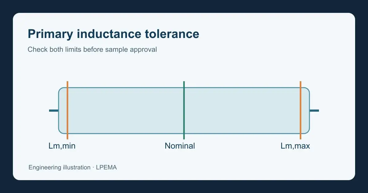
Flyback transformer primary inductance tolerance describes the allowed range around a specified nominal magnetizing inductance. A catalog value alone does not establish the converter’s worst-case current or output capability. Engineers should check the minimum and maximum inductance against their controller, input range, operating mode, core design, and sample test conditions. This guide explains the first-pass calculations and the evidence to request from a compact EP or EFD transformer supplier.
Why flyback transformer primary inductance tolerance matters
While the primary switch is on, the primary magnetizing current changes approximately as ΔI = Vpri × ton / Lm, provided the magnetic core remains in its intended operating region. At the same applied voltage and on-time, a lower Lm produces a steeper current ramp. The converter’s current limit, switching mode, and control response determine what happens next. A higher Lm produces a shallower ramp and can change the energy delivered per switching cycle under a given control scheme. Do not treat either tolerance limit as automatically good or bad.
The familiar E = ½ × Lm × Ipk² describes stored magnetic energy at a given peak current. It does not mean raising Lm always raises available output power: peak current, frequency, losses, reset, and controller limits change with the design. Texas Instruments’ flyback design discussion connects inductance with current ramp and operating mode. Use the controller’s own design procedure for final limits.
Specify the measurement, not just the number
An inductance limit is meaningful only with a defined winding connection, test frequency, signal level, temperature or reference condition, and treatment of other windings. Ask whether the value is small-signal primary magnetizing inductance or a large-signal parameter inferred from operation. Keep leakage inductance separate from Lm: the two have different circuit effects and often use different measurement connections.
For an example of how a flyback design specifies primary inductance tolerance, see the Power Integrations AN-88 application note. Its example tolerance belongs to that design context; it is not an LPEMA catalog-wide specification. The Power Integrations AN-18 application note also discusses core gapping and why a tightly specified gap dimension is not the same as a controlled inductance requirement.
Calculate both ends of the inductance range
If a drawing states nominal Lm and a symmetric tolerance ±t, calculate Lm,min = Lm,nom × (1 − t) and Lm,max = Lm,nom × (1 + t). These are specification limits, not measured LPEMA values. For illustration only, a hypothetical 100 µH design at ±10% has a 90–110 µH window. At the same applied voltage and on-time, the 90 µH edge has about 22% more current ramp than the 110 µH edge. That comparison does not predict actual peak current without the initial primary current and controller behavior.
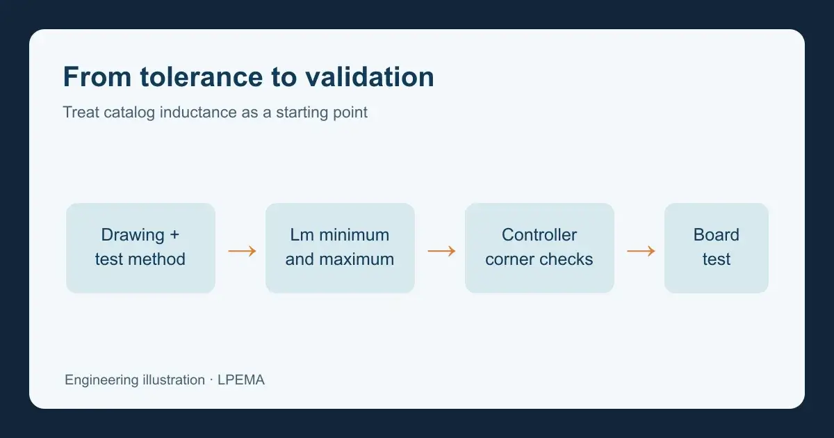
For both the minimum and maximum inductance limits, check minimum input with maximum load, maximum input, light load, startup, and relevant fault recovery. Record the controller’s minimum and maximum switching frequency, on-time, current-sense threshold, and compensation behavior. In continuous conduction mode the primary current starts above zero, so a simple zero-current ramp does not describe the whole waveform. In discontinuous conduction mode verify that demagnetization completes under the stated conditions. Compare peak and RMS current, core flux, switch and rectifier stress, and temperature against the complete design limits.
Apply the window to an EP or EFD shortlist
The LPEMA EP transformer table lists compact EP candidates with an inductance field. Use it as a shortlist, then request the controlled drawing and the tolerance and test method for the exact part number. The EP10 PoE flyback sourcing guide explains why a common core size does not make two parts electrically or mechanically interchangeable. For low-profile candidates, check the EFD product table and request the actual drawing.
Do not infer a tolerance, current rating, saturation point, or application approval from a catalog inductance field. If a competitor part is the starting point, compare controlled drawings and measurements at matching conditions. No direct replacement follows from a similar nominal Lm.
Sample acceptance checklist
- Identify the exact LPEMA part number, drawing revision, winding pin map, and polarity.
- Record nominal Lm, minimum and maximum limits, frequency, signal level, connection, and temperature condition.
- Measure representative samples with the agreed fixture and document the results.
- Check the minimum and maximum inductance cases in the converter model using controller limits and worst-case input and load.
- Validate actual primary current, switching mode, output regulation, voltage stress, and temperature on the assembled board.
- Approve the part only against the system’s own electrical, insulation, and production requirements.
FAQ: Is a tighter primary inductance tolerance always better?
No. The useful range is the range the converter design can tolerate, considering manufacturing variation and cost. Ask for a justified limit rather than a generic percentage.
FAQ: Can I compare two catalog inductance values directly?
Only as a first filter. Confirm measurement conditions, tolerance, winding map, transformer leakage inductance (Llk), and the converter operating window before comparing candidate transformers.
FAQ: Does inductance tolerance equal saturation-current tolerance?
No. Small-signal Lm tolerance does not define the large-signal saturation behavior. Obtain the relevant current or volt-time evidence and test worst-case waveforms in the target circuit.
Need an EP or EFD flyback sample review? Send LPEMA the controller, input range, output and load matrix, switching mode, target Lm window, drawing and footprint constraints, and your measurement method. Request a controlled drawing and sample plan before approval through the LPEMA contact page.

