
Gate Drive Transformer Selection Guide for SiC, IGBT, and MOSFET Designs
1. Start With the Right Kind of Transformer
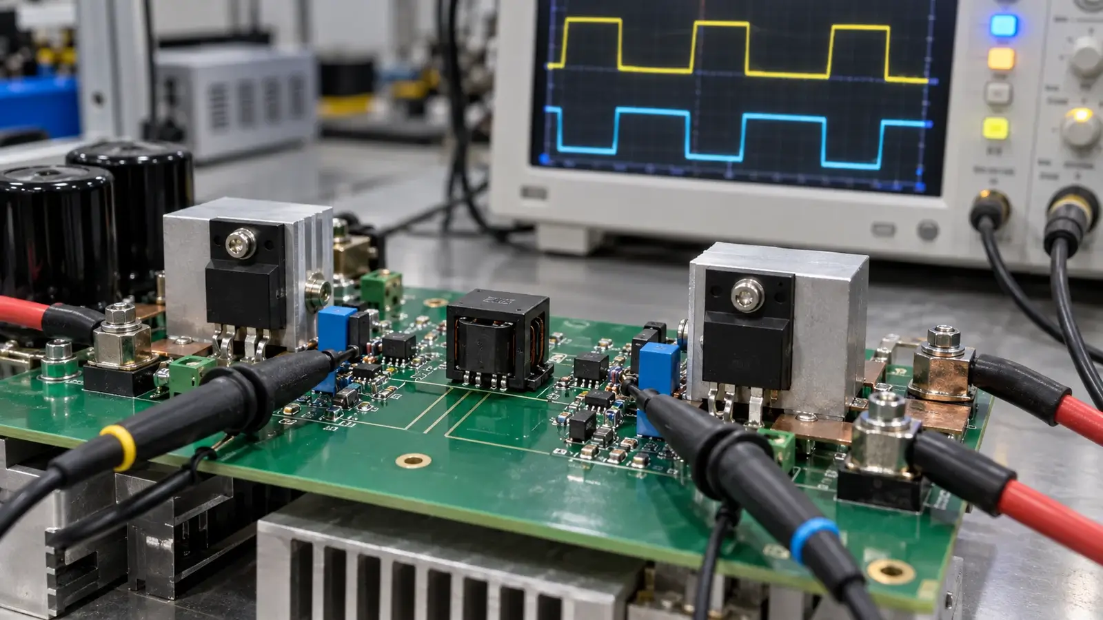
A gate drive transformer looks simple: one small ferrite core, one primary winding, and one or more secondary windings. Its job is to carry an isolated pulse from the controller to the gate of a power switch.
That description hides the difficult part. The transformer must reproduce a fast pulse without losing amplitude, changing timing, ringing hard enough to cause false turn-on, or walking into saturation after a duty-cycle transient.
Before selecting one, make sure you are looking at the right component. Two products are often sold under similar names:
| Product | What Crosses the Isolation Barrier | Typical Function |
| Gate drive transformer (GDT) | The gate-control pulse itself | Directly drives one or more MOSFET, IGBT, or SiC gates |
| Auxiliary gate-drive transformer | Power for an isolated driver IC | Generates isolated bias rails such as +15 V/-4 V |
This guide covers the first type: the pulse transformer in the signal path. An auxiliary gate-drive power transformer has a different design objective and should not be selected with the same checklist.
2. When a Gate Drive Transformer Makes Sense
A GDT is attractive when a design needs galvanic isolation, high peak gate current, low steady-state power consumption, and matched drive for two or more switches. A single primary can also support multiple secondaries for half-bridge, full-bridge, or push-pull arrangements.
Common applications include:
- Isolated gate drive in full-bridge and phase-shifted full-bridge converters
- High-side and low-side drive in half-bridge stages
- Synchronous rectifier drive
- Industrial motor drives and welding power supplies
- IGBT and MOSFET modules in inverters and UPS systems
- Selected SiC switching stages where pulse fidelity and common-mode behavior are verified
A GDT is not the automatic answer for every isolated driver. It cannot pass DC. Long static on-times, very wide duty-cycle ranges, burst modes, startup states, and independent fault control can be easier to manage with a digital isolator plus an isolated bias supply.
The first selection question is therefore not “What turns ratio do I need?” It is “Can my drive waveform maintain transformer flux balance under every operating state?”
3. Volt-Second Rating: The First Number to Check
Every pulse applied to the primary changes the magnetic flux in the core. The applied volt-second product is:
V × tON
For a 15 V pulse lasting 2 µs, the transformer sees 30 Vµs. The selected GDT must support more than this value under the worst combination of drive voltage, maximum pulse width, minimum switching frequency, and transient duty-cycle error.
| Design Input | Example |
| Primary drive amplitude | 15 V |
| Maximum uninterrupted pulse width | 2 µs |
| Applied volt-second product | 30 Vµs |
| Practical selection target | Greater than 30 Vµs, with transient margin |
Do not calculate from nominal 50% duty cycle alone. Startup pulses, current-limit events, pulse skipping, and control-loop transients can create temporary asymmetry. Even a small average DC voltage causes flux walking; repeated unequal pulses eventually move the core toward saturation.
The reset network and drive topology matter as much as the transformer rating. Bipolar drive naturally helps balance the core. Single-ended drive normally needs a coupling capacitor, clamp, or another defined reset path. Verify the primary waveform on the real board during startup and protection events—not only at steady state.
4. Turns Ratio Sets Gate Voltage, But It Does Not Guarantee It
Most GDTs use a 1:1 ratio because the driver supply is already close to the required gate voltage. Ratios such as 2:1, 2.5:1, or multiple matched secondaries are useful when the controller-side voltage and gate requirement differ or when one primary drives several switches.
The ideal relationship is simple:
Vsecondary ≈ Vprimary × Nsecondary / Nprimary
The voltage seen at the gate is lower and less clean than the ideal value because of winding resistance, leakage inductance, magnetizing current, gate resistance, diode drops, and gate charge. Treat the ratio as a starting point, then simulate and measure the loaded waveform.
Device requirements also differ:
| Switch Type | Typical Design Priority | GDT Implication |
| Silicon MOSFET | Fast charge/discharge with controlled ringing | Low leakage inductance and adequate peak current |
| IGBT | Strong turn-off and false-turn-on control | A negative off-voltage may be needed; check reset and clamp network |
| SiC MOSFET | Very fast edges and high dv/dt immunity | Leakage inductance and winding capacitance become especially sensitive |
Always use the power-device manufacturer’s recommended gate-voltage range. “15 V gate drive” is not a universal rule, particularly for SiC devices from different vendors.
5. The Four Parasitics That Shape the Real Pulse
#### Magnetizing Inductance
Magnetizing inductance determines how much current the transformer draws simply to establish flux. If it is too low, magnetizing current rises during each pulse, loads the driver, tilts the secondary waveform, and increases the risk of saturation.
Higher is generally helpful, but it cannot be considered alone. More turns can raise magnetizing inductance while also increasing winding capacitance, resistance, and leakage.
#### Leakage Inductance
Leakage inductance sits in series with the gate-current path. It resists rapid changes in current, slows turn-on and turn-off, and resonates with the MOSFET or IGBT input capacitance. The result may be delayed edges, overshoot, undershoot, or ringing across the gate threshold.
Low leakage inductance is essential for fast switching. Closely coupled, bifilar, or trifilar windings can help, but that leads directly to the next trade-off.
#### Interwinding Capacitance
Primary-to-secondary capacitance provides a path for common-mode displacement current when the switch node changes rapidly. In a SiC stage with high dv/dt, even a few picofarads can inject current into the controller ground or secondary gate loop.
Winding methods that reduce leakage often increase capacitive coupling. The best transformer is not the one with the lowest possible value in one column; it is the one with the right balance for the switching speed, layout, and common-mode environment.
#### Winding Resistance
DCR is less dominant than in a power transformer because average power is small, but the GDT carries short, high peak currents. Excess resistance reduces gate amplitude and damps the pulse. It can be useful damping, but it should be intentional and coordinated with the external gate resistor.
6. Isolation Is More Than a Hi-Pot Number
The transformer’s test voltage must match the actual insulation requirement of the system. A 1,500 VDC production test, a 2,500 VAC withstand rating, and reinforced insulation are not interchangeable claims.
Define at least:
- Working voltage across the isolation barrier
- Required basic or reinforced insulation
- Hi-Pot test voltage, waveform, and duration
- Creepage and clearance requirements
- Pollution degree and overvoltage category
- Insulation system and applicable safety standard
- Expected common-mode transient environment
For high-voltage SiC and IGBT systems, package construction and PCB spacing can become the limiting factors even when the windings pass the requested dielectric test.
7. A Practical GDT Selection Sequence
Use this order. It prevents a convenient footprint or turns ratio from hiding a fundamental magnetic limitation.
| Step | Question | Evidence to Request |
| 1 | Can a transformer carry this waveform? | Min/max duty cycle, burst behavior, startup and fault timing |
| 2 | Will the core remain balanced? | Reset method and worst-case primary volt-seconds |
| 3 | Is gate voltage correct under load? | Turns ratio, device gate charge, loaded waveform |
| 4 | Are switching edges acceptable? | Leakage inductance, magnetizing inductance, scope test |
| 5 | Is common-mode current controlled? | Interwinding capacitance and dv/dt test conditions |
| 6 | Does isolation meet the system standard? | Working voltage, test voltage, creepage, clearance, insulation class |
| 7 | Can it be manufactured consistently? | Tolerances, test plan, winding construction, sample report |
LPEMA’s current gate drive transformer range includes EP5, EP6, EP7, EFD17, SMD CASE, and ER constructions, with single and multiple-secondary configurations. The right construction depends on the electrical and insulation requirements; core family alone is not a selection specification.
8. Common Selection Mistakes—and What They Look Like on the Scope
Selecting by turns ratio only. The no-load voltage looks correct, but the gate waveform collapses or tilts when connected to the real device.
Ignoring maximum pulse width. The circuit works at nominal frequency, then the core saturates during startup, pulse skipping, or current limit. Primary current rises sharply near the end of the pulse.
Chasing minimum leakage without checking capacitance. Gate edges improve, but common-mode current creates controller noise or false triggering at high dv/dt.
Using a 50% duty-cycle assumption as a reset strategy. Small timing errors accumulate into flux walking. One polarity clips before the other.
Treating Hi-Pot voltage as the entire insulation design. The transformer passes a short dielectric test but the package or PCB does not meet required creepage and clearance.
Testing only at room temperature. Core characteristics, gate threshold behavior, and switching speed shift at operating temperature. A stable 25°C waveform may not remain stable at the application’s hot and cold limits.
9. What to Put in a Gate Drive Transformer RFQ
“Need a 1:1 gate drive transformer” is not enough to quote or design the part correctly. Send the information below:
| RFQ Field | What to Provide |
| Application and topology | Half bridge, full bridge, push-pull, synchronous rectifier, motor drive, etc. |
| Power switch | Exact MOSFET, IGBT, or SiC part number |
| Primary waveform | Amplitude, polarity, frequency range, duty-cycle range, and maximum pulse width |
| Reset method | Bipolar drive, coupling capacitor, clamp, or other circuit |
| Secondary requirement | Number of outputs, gate on/off voltages, turns ratio |
| Gate circuit | Gate resistance, clamp components, peak source/sink current if known |
| Magnetic limits | Minimum magnetizing inductance, maximum leakage inductance and capacitance if specified |
| Isolation | Working voltage, test voltage/time, insulation class, creepage and clearance |
| Environment | Ambient range, cooling, altitude, humidity, applicable standard |
| Mechanical | Maximum dimensions, footprint, pinout, mounting and packaging |
If you have a reference part, include its manufacturer and full part number—but also include the circuit requirements. A dimensional cross-reference is not automatically electrically equivalent.
📌 For a complete custom transformer inquiry checklist, see our transformer specification and RFQ guide.*
10. FAQ—Gate Drive Transformer Questions
What is a gate drive transformer?
A gate drive transformer is a pulse transformer that provides galvanic isolation while transferring gate-control pulses from a driver circuit to one or more power semiconductor gates.
Is a gate drive transformer the same as an isolated gate-driver power transformer?
No. A GDT transfers the control pulse itself. An auxiliary gate-drive transformer transfers power to an isolated driver IC that recreates the control signal locally.
How do I calculate the required volt-second rating?
Multiply the maximum primary pulse amplitude by the longest uninterrupted pulse duration. Then add margin for component tolerances, startup, control transients, and flux imbalance.
Why does a gate drive transformer saturate?
The usual causes are excessive applied volt-seconds, inadequate reset, unequal positive and negative pulses, or a DC component in the primary waveform.
Why is low leakage inductance important?
Leakage inductance opposes rapid gate-current changes. Too much slows switching and can resonate with gate capacitance, causing overshoot and ringing.
Why does interwinding capacitance matter in SiC designs?
High switch-node dv/dt drives displacement current through the transformer capacitance. This can disturb the gate loop or controller reference and contribute to false turn-on.
Can one GDT drive both switches in a half bridge?
Yes, a transformer with two suitable secondary windings can drive high-side and low-side switches, provided polarity, dead time, reset, gate voltage, and fault behavior are correctly designed.
Can LPEMA cross-reference an existing GDT?
LPEMA can evaluate reference parts against its EP5, EP6, EP7, EFD17, SMD CASE, and ER product capabilities. Electrical equivalence must be confirmed from the complete specification and application conditions, not the footprint alone.
11. Bottom Line
A gate drive transformer is not selected by turns ratio and isolation voltage alone.
Start with the real waveform. Verify volt-second balance and reset, then evaluate magnetizing inductance, leakage inductance, interwinding capacitance, loaded gate voltage, and the complete insulation system. Finally, test the waveform on the actual power stage across startup, normal operation, faults, and temperature.
If you are selecting a GDT for a MOSFET, IGBT, or SiC design, send LPEMA the switch part number, primary waveform, gate-voltage target, isolation requirement, and mechanical limits. We can recommend an existing construction or develop a custom sample for your circuit.
Author

Please Contact Us
